Unification type cap assembly containing protection circuit board and secondary battery comprising the same

a protection circuit board and secondary battery technology, applied in the direction of batteries, primary cell maintenance/service, sustainable manufacturing/processing, etc., can solve the problems of high manufacturing cost, high price and incompatibility, and increase manufacturing cost, so as to reduce the frequency of defective products and facilitate battery manufacturing

Active Publication Date: 2010-01-19
LG ENERGY SOLUTION LTD
View PDF5 Cites 0 Cited by
  • Summary
  • Abstract
  • Description
  • Claims
  • Application Information

AI Technical Summary

Benefits of technology

[0019]Therefore, the present invention has been made in view of the above problems, and it is an object of the present invention to provide an integral cap assembly, which comprises a top cap mounted as a base plate to an opening of the upper end of a battery can, and a cap subassembly including a protective circuit module and the like integrally mounted on the top cap, thereby allowing easy manufacturing of a battery while remarkably reducing the frequency of defective products.
[0020]It is another object of the invention to provide a method of manufacturing a battery through a simple assembly using the cap assembly.
[0023]The cap assembly of the invention is provided as an independent member, and characterized in that the cap subassembly comprising the protective circuit module, and a cap housing are integrally mounted on the top cap. Accordingly, the battery can be easily manufactured by inserting an electrode assembly comprising a cathode, a separator and an anode into the battery can, and mounting the cap assembly of the invention on the opening of the battery can. As such, the cap assembly provided as the independent member, which comprises the cap subassembly integrally mounted on the top cap acting as the base plate, is novel.
[0024]Here, the term “cap subassembly” means all components mounted on the top cap while constituting an upper portion of the battery, and may comprise, for example, a protective circuit module for preventing over-current, over-discharge, and over-charge of the battery, a cap housing for covering an outer surface of the protective board, and the like. Optionally, the cap subassembly may comprise an electrode lid for electrical connection, an insulating member for preventing electrical short, and safety elements including, a PTC element, a bimetal, a fuse, etc.
[0027]As such, the manufacture of the cap assembly through the insert injection molding can be performed by molding the cap assembly in a state wherein the protective circuit module is not electrically connected to the battery body, that is, in a state wherein the protective circuit module is mounted on the top cap having the two electrodes formed thereupon without application of power thereto. Thus, the insert injection molding of the invention allows the cap assembly to be easily molded by use of a typical molten resin while ensuring electrical stability during the process. Additionally, the insert injection molding of the invention eliminates a coating process for preventing an electrical short, and a danger of electrical damage to the protective circuit. Furthermore, as the protective circuit module is not molded together with the battery body within the mold, there are no problems, such as instability of the battery body due to application of pressure or heat to the battery body occurring when the protective circuit is molded together with the battery body within the mold, and defects due to dimensional errors of the battery body inserted into the mold. Instead, the insert injection molding of the cap assembly provides an advantage of reduction in size of the mold due to the fact that it is unnecessary to insert the battery body into the mold.
[0028]During insert injection molding, the top cap and the cap subassembly are formed into an integral body via solidification of the molten resin. At this time, in order to enhance coupling force to the resinous injection material, the top cap preferably has one or more fixing recesses formed thereon to allow a portion of the molten resin to infiltrate thereto. Accordingly, the molten resin infiltrating the fixing recesses acts to enhance the coupling force between the top cap and the resinous injection material after being solidified.

Problems solved by technology

However, since the hard cap battery 10 requires a case (housing) 11 that serves to house a battery body embedded therein and is designed to have a shape according to a kind of an associated device, it has problems of higher price and incompatibility.
First, there is an increasing demand for a smaller and lighter battery as a result of miniaturization and compactness of devices, and thus it is necessary to manufacture a case corresponding to such a battery through an ultra-precise thin film injection molding, which has a technological difficulty and results in an increase of manufacturing costs.
Second, the secondary battery requires a number of processes for mounting the PTC element, the nickel plates, the protective circuit module, the upper and lower cases, and the like, and is difficult to assemble, thereby providing high frequency of defective products and increasing the manufacturing costs.
Third, since the upper and lower cases are mainly welded to each other through supersonic welding, it is necessary for the pack to have a predetermined thickness or more for the supersonic welding, which becomes a factor of impedance to the miniaturization and compactness of the battery. Further, since minute movement of the upper and lower cases occurs during the supersonic welding, defectiveness of the products is high, and constant operator management is necessary.
However, since a cap assembly 60 is molded integrally with the battery body 21 within the mold 40, this method has several problems as follows.
Third, if the battery body 21 has a high temperature within the molding space 40, the battery can be susceptible to change in electrical characteristics and be subjected to a danger of explosion.

Method used


Image

  • Unification type cap assembly containing protection circuit board and secondary battery comprising the same
  • Unification type cap assembly containing protection circuit board and secondary battery comprising the same
  • Unification type cap assembly containing protection circuit board and secondary battery comprising the same

Examples


Embodiment Construction

[0055]Preferred embodiments of the invention will now be described with reference to the drawings. It should be noted that the embodiments are disclosed for the purpose of illustration, and do not limit the scope of the invention.

[0056]FIG. 8 is an exploded perspective view of a secondary battery in accordance with one preferred embodiment of the invention, and FIG. 9 is a perspective view of the secondary battery of FIG. 8 in an assembled state.

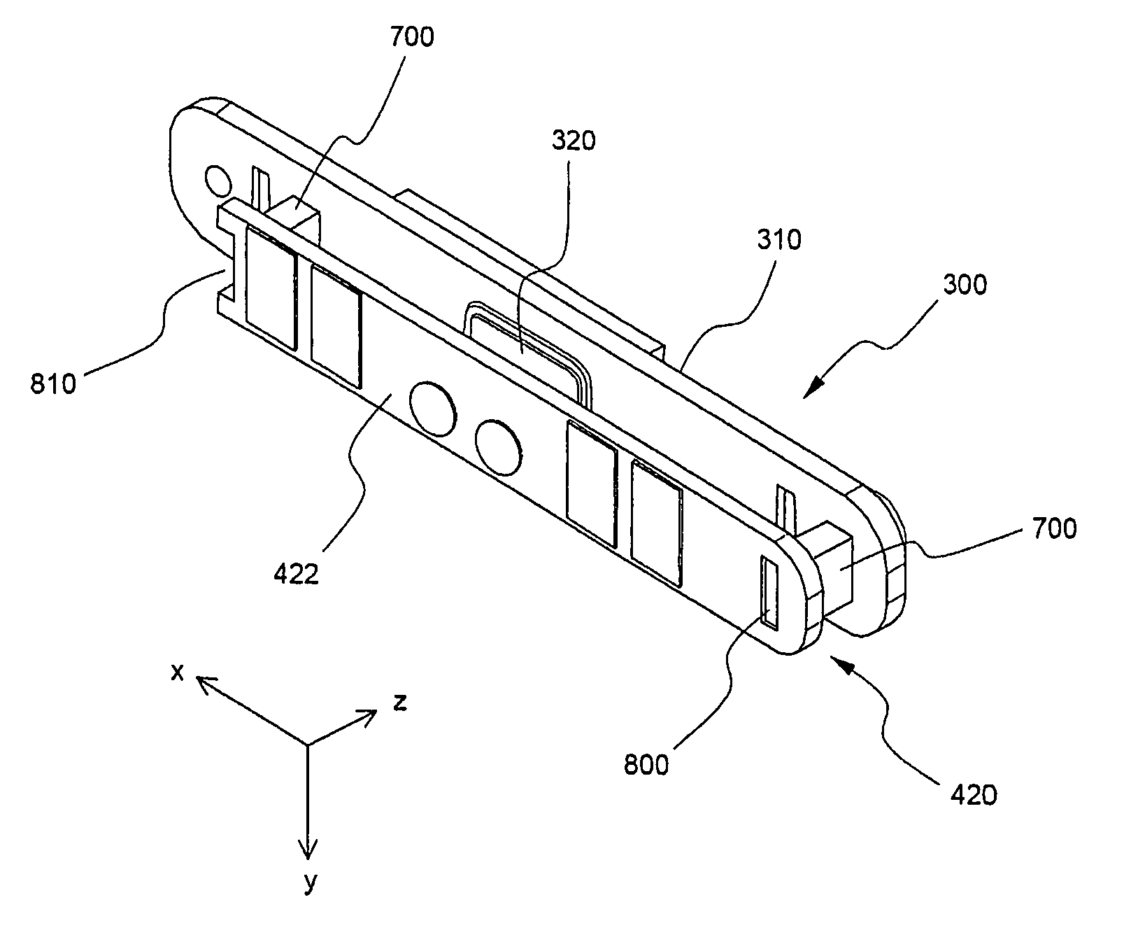
[0057]Referring to FIGS. 8 and 9, a secondary battery 100 comprises a battery can 200 into which an electrode assembly 210 consisting of a cathode, an anode and a separator is inserted, a top cap 300 mounted on an opening of an upper end of the can 200, and a cap subassembly 400 mounted on the top cap 300.

[0058]The top cap 300 comprises a plate 310 made of an electrically conductive material, such as aluminum, a protruded terminal 320 formed on the conductive plate 310 so as to be insulated from the conductive plate 310 and connected to the ...


PUM

PropertyMeasurementUnit
conductiveaaaaaaaaaa
frequencyaaaaaaaaaa
thicknessaaaaaaaaaa

Abstract

An integral cap assembly comprising a top cap mounted as a base plate to an opening of a battery can and a cap subassembly including a protective circuit module and the like integrally mounted on the top cap, a method for manufacturing a secondary battery comprising the same, and a secondary battery manufactured thereby are disclosed. The cap assembly is provided as an integral member comprising the top cap acting as the base plate, and the cap subassembly having the protective circuit module provided thereon, thereby simplifying a manufacturing process of the battery while minimizing frequency of defective products. Additionally, the integral cap assembly is manufactured through insert injection molding, thereby providing notable advantages over the conventional technology.

Description

FIELD OF THE INVENTION[0001]The present invention relates to an integral cap assembly for a battery, and a secondary battery comprising the same, and, more particularly, to an integral cap assembly, which comprises a top cap mounted as a base plate to an opening of the upper end of a battery can, and a cap subassembly including a protective circuit module and the like integrally mounted on the top cap, a method for manufacturing a secondary battery comprising the same, and a secondary battery manufactured thereby.BACKGROUND OF THE INVENTION[0002]A rechargeable secondary battery is generally classified into hard cap batteries and internal batteries. FIG. 1 shows a representative example of the hard cap battery. Referring to FIG. 1, a hard cap battery 10 is provided as a detachable part of a device 12, and thus has an advantage of convenience in mounting of the battery to the device 12. However, since the hard cap battery 10 requires a case (housing) 11 that serves to house a battery ...

Claims


Application Information

Patent Timeline
Patent Type & Authority Patents(United States)
IPC IPC(8): H01M2/00H01M6/50H01M10/04H01M10/42H01M50/147H01M50/583
CPCH01M2/0404H01M10/425H01M10/0436H01M2/34Y10T29/4911H01M2200/10Y02E60/10H01M50/147Y02P70/50H01M50/583H01M50/572H01M50/20H01M10/052
Inventor KIM, HYUNGCHANKIM, HEE GYUCHO, YONG-HOCHUNG, JAE SIK
Owner LG ENERGY SOLUTION LTD
Why Eureka
Try Eureka