Composite material, and light emitting element and light emitting device using the composite material

a technology of composite materials and light emitting elements, applied in the direction of luminescent compositions, thermoelectric devices, chemistry apparatus and processes, etc., can solve the problems of power consumption, low transmittance, and still many problems, and achieve excellent visible light transmittance, excellent carrier transport property and carrier injection property, and the effect of reducing the drive voltag

Inactive Publication Date: 2010-01-19
SEMICON ENERGY LAB CO LTD
View PDF23 Cites 49 Cited by
  • Summary
  • Abstract
  • Description
  • Claims
  • Application Information

AI Technical Summary

Benefits of technology

[0013]It is an object of the present invention to provide a composite material of an organic compound and an inorganic compound, which has an excellent carrier transport property and carrier injection property into the organic compound and also has excellent visible light transmittance.
[0014]It is another object to provide a light emitting element with low drive voltage by using the composite material for a current-excitation light emitting element. It is still another object to provide a light emitting device with low power consumption by manufacturing a light emitting device using the light emitting element.
[0015]As a result of keen examinations, the present inventors have found that the objects can be achieved by using a layer containing an organic compound and an inorganic compound which exhibits an electron accepting property to the organic compound.

Problems solved by technology

However, there are still many issues.
One of the issues is a reduction in power consumption.
However, as stated in Reference 1, PANI has a problem in that transmittance thereof becomes lower as a thickness thereof increases.
In other words, there is a problem with transparency of a material itself which is used for the buffer layer; therefore, light generated inside an element cannot be extracted efficiently.
However, as can be understood from the embodiment, the mixed layer of an organic compound and metal oxide, which is disclosed in Reference 2, has a strong absorption peak in a visible light region (in the vicinity of 500 nm) as well as an infrared region, and also has a problem with transparency.
Consequently, after all, light generated inside the element cannot be extracted efficiently, and luminous efficiency of the element is lowered.

Method used


Image

  • Composite material, and light emitting element and light emitting device using the composite material
  • Composite material, and light emitting element and light emitting device using the composite material
  • Composite material, and light emitting element and light emitting device using the composite material

Examples


embodiment 1

[0143]In this embodiment, a composite material of the present invention is explained. The composite material of the invention contains a carbazole derivative represented by the following general formula (1) and an inorganic compound.

[0144]

[0145]In the formula, R11 and R13 may be either the same or different, each of which represents any one of hydrogen, an alkyl group having 1 to 6 carbon atoms, an aryl group having 6 to 25 carbon atoms, a heteroaryl group having 5 to 9 carbon atoms, an arylalkyl group, and an acyl group having 1 to 7 carbon atoms; Ar11 represents one of an aryl group having 6 to 25 carbon atoms and a heteroaryl group having 5 to 9 carbon atoms; R12 represents any one of hydrogen, an alkyl group having 1 to 6 carbon atoms, and an aryl group having 6 to 12 carbon atoms; R14 represents any one of hydrogen, an alkyl group having 1 to 6 carbon atoms, an aryl group having 6 to 12 carbon atoms, and a substituent represented by General Formula (2). In the substituent repre...

embodiment 2

[0188]A light emitting element of the present invention has a plurality of layers between a pair of electrodes. The plurality of layers is a laminate of a combination of layers formed of a material having a high carrier injection property and a material having a high carrier transport property such that a light emitting region is formed apart from the electrodes, in other words, such that carriers are recombined in a portion distant from the electrodes.

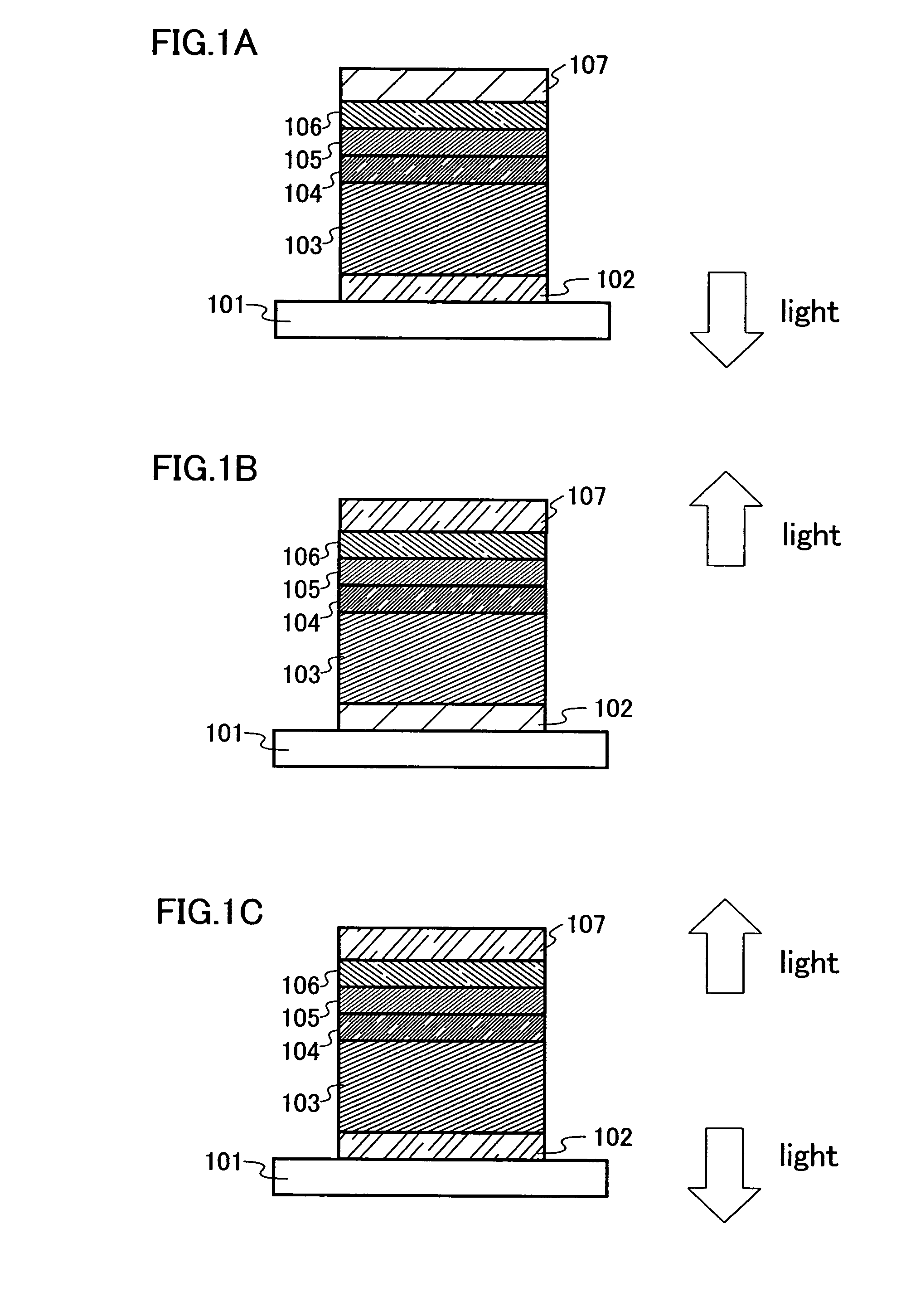
[0189]One mode of the light emitting element of the invention is hereinafter explained with reference to FIG. 1A.

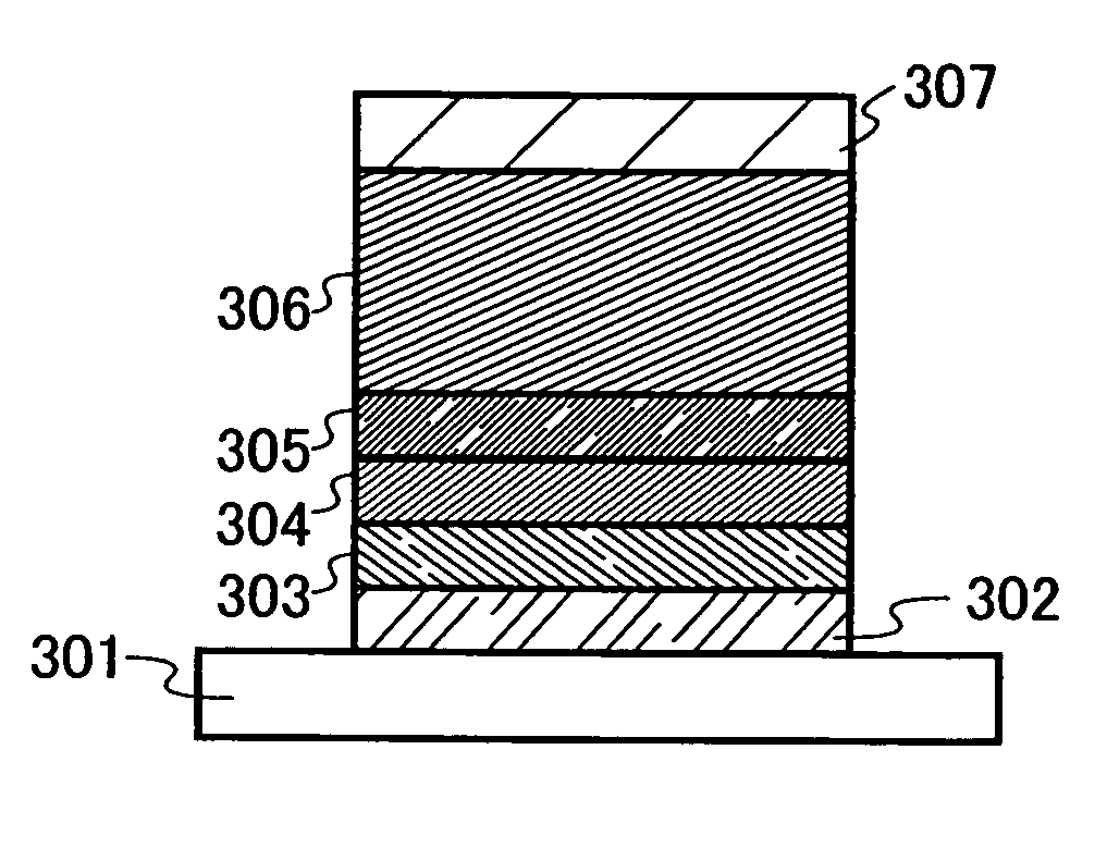
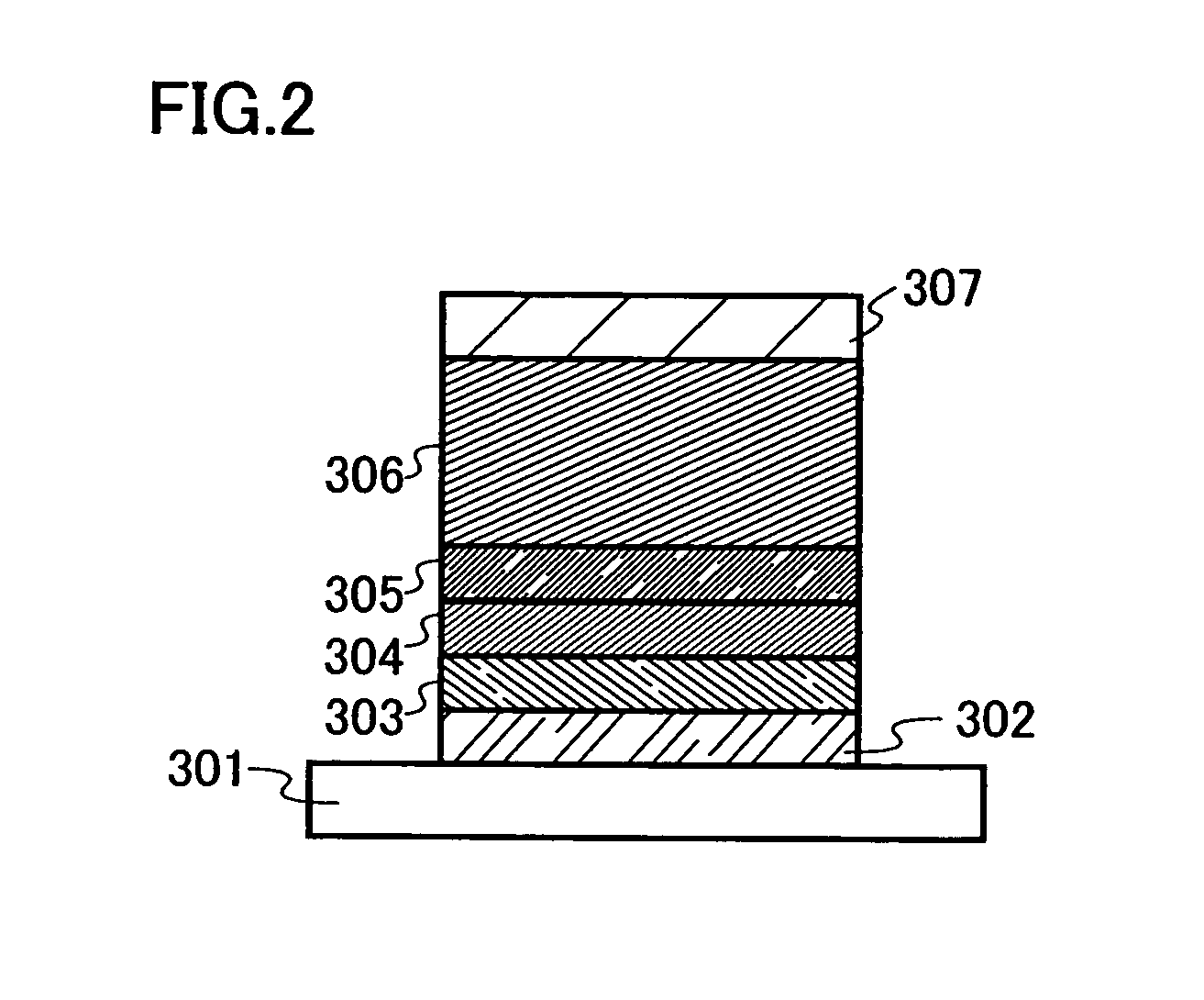
[0190]In this embodiment, the light emitting element includes a first electrode 102, a first layer 103, a second layer 104, a third layer 105, and a fourth layer 106 which are sequentially laminated over the first electrode 102, and a second electrode 107 which is further provided thereover. Note that in this embodiment, explanation is made hereinafter assuming that the first electrode 102 functions as an anode and the seco...

embodiment 3

[0214]In this embodiment, a light emitting element having a structure different from that described in Embodiment 2 is explained with reference to FIGS. 5A to 5C and 6A to 6C. In a structure to be described in this embodiment, a layer containing the composite material of the invention can be provided to be in contact with an electrode serving as a cathode.

[0215]An example of a structure of a light emitting element of the invention is shown in FIG. 5A. In the structure, a first layer 411, a second layer 412, and a third layer 413 are laminated between a first electrode 401 and a second electrode 402. In this embodiment, the case where the first electrode 401 functions as an anode and the second electrode 402 functions as a cathode, is explained.

[0216]The first electrode 401 and the second electrode 402 can employ the same structure as that in Embodiment 2. The first layer 411 is a layer which contains a material having a high light emitting property. The second layer 412 is a layer w...


PUM


Abstract

An object is to provide a light emitting element with low drive voltage which contains an organic compound and an inorganic compound. One feature of a light emitting element of the present invention is to include a layer containing a light emitting material between a pair of electrodes, in which the layer containing a light emitting material has a layer containing a carbazole derivative represented by General Formula (1) and an inorganic compound which exhibits an electron accepting property to the carbazole derivative represented by General Formula (1). With such a structure, the inorganic compound accepts electrons from the carbazole derivative, carriers are generated internally, and a drive voltage of the light emitting element can be reduced.

Description

BACKGROUND OF THE INVENTION[0001]1. Field of the Invention[0002]The present invention relates to a composite material of an organic compound and an inorganic compound, which has an excellent carrier transport property and carrier injection property into the organic compound and also has excellent visible light transmittance. The invention also relates to a current-excitation light emitting element using the composite material. The invention further relates to a light emitting device having the light emitting element.[0003]2. Description of the Related Art[0004]In recent years, a light emitting element using a light emitting organic compound has been actively researched and developed. A basic structure of this light emitting element is that a layer containing a light emitting organic compound is sandwiched between a pair of electrodes. By applying a voltage to this element, electrons and holes are separately injected from the pair of electrodes into the layer containing a light emitt...

Claims


Application Information

Patent Timeline
Patent Type & Authority Patents(United States)
IPC IPC(8): H01L35/24H01L51/00
CPCC09K11/06H05B33/22C09K2211/1029H10K85/636H10K85/6572H10K50/17H10K71/00H10K71/10
Inventor IWAKI, YUJISEO, SATOSHIKUMAKI, DAISUKENAKASHIMA, HARUEKOJIMA, KUMI
Owner SEMICON ENERGY LAB CO LTD
Why Eureka
Try Eureka