
Multilayer ceramic capacitor

a multi-layer ceramic and capacitor technology, applied in the direction of fixed capacitors, fixed capacitor details, stacked capacitors, etc., can solve the problem that the reliability of multi-layer ceramic capacitors sintered with such barium titanate powders is low in a highly accelerated life tes

Inactive Publication Date: 2010-01-26
KYOCERA CORP
View PDF13 Cites 14 Cited by
  • Summary
  • Abstract
  • Description
  • Claims
  • Application Information

AI Technical Summary

Benefits of technology

[0007]Barium titanate powders prepared by the hydrothermal synthetic process are mixed with various additives such as a glass component and an anti-reducing agent and the resulting mixture is fired in a reducing atmosphere. Numerous pores are formed in all parts of barium titanate crystal grains, such as near the grain surface and in the center region of the grain (see FIG. 8). A multilayer ceramic capacitor having ceramic dielectric layers sintered using such barium titanate powders has low reliability in a highly accelerated life test involving application of DC voltage at high temperature.
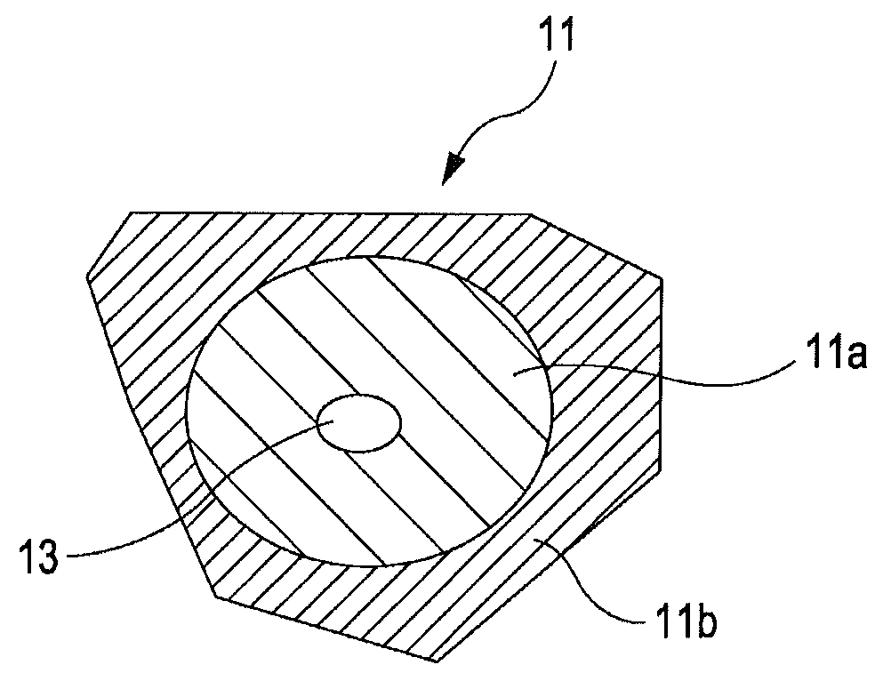
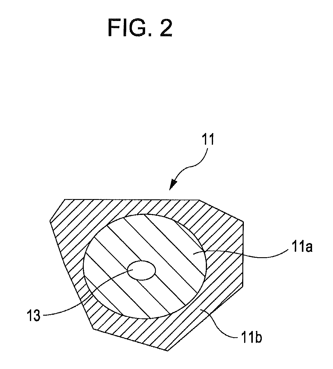
[0029]First, since the barium titanate crystal grains at the core 11a have a tetragonal crystal structure, the core exhibits ferroelectricity. Pores in the core exhibit a pinning effect and suppress movement of the domain walls. Thus, the barium titanate crystal grains having pores in the core are suppressed from entering a single domain state in the c-axis direction of the tetragonal phase, i.e., the direction of applied voltage. As a result, the decrease in capacitance of the multilayer ceramic capacitor during DC bias application can be suppressed, and good DC bias characteristics can be achieved.

Problems solved by technology

A multilayer ceramic capacitor having ceramic dielectric layers sintered using such barium titanate powders has low reliability in a highly accelerated life test involving application of DC voltage at high temperature.

Method used


Image

  • Multilayer ceramic capacitor
  • Multilayer ceramic capacitor
  • Multilayer ceramic capacitor

Examples


examples

[0070]A multilayer ceramic capacitor was prepared as follows. A mixture of a BT powder (BaTiO3) and a BCT powder (Ba1-xCaxTiO3, x=0.05) was used as the dielectric powder. The site ratio A / B was 1.003. In Table 1, the dielectric powder used in the oxalate process and the hydrothermal synthetic process was a 1:1 (mol) mixture of the BT powder and the BCT powder. The dielectric powder used in the alkoxide process was the BT powder alone. The average particle diameters of the BT powder and the PCT powder used are shown in Table 1. A mixture of 30 mol % BaO, 20 mol % CaO, and 50 mol % SiO2 and a mixture of 90 mol % SiO2 and 10 mol % of B2O3 having a melting point of 950° C. were used as sintering aids. In 100 mol % of the barium titanate powder, the MgO content was 1 mol %, the MnO content was 0.3 mol %, and the rare earth element content was 1 mol % on an oxide basis. These additives were subjected to a wet process so as to coat the surfaces of the barium titanate particles and were aff...


PUM

PropertyMeasurementUnit
grain diameteraaaaaaaaaa
thicknessaaaaaaaaaa

Abstract

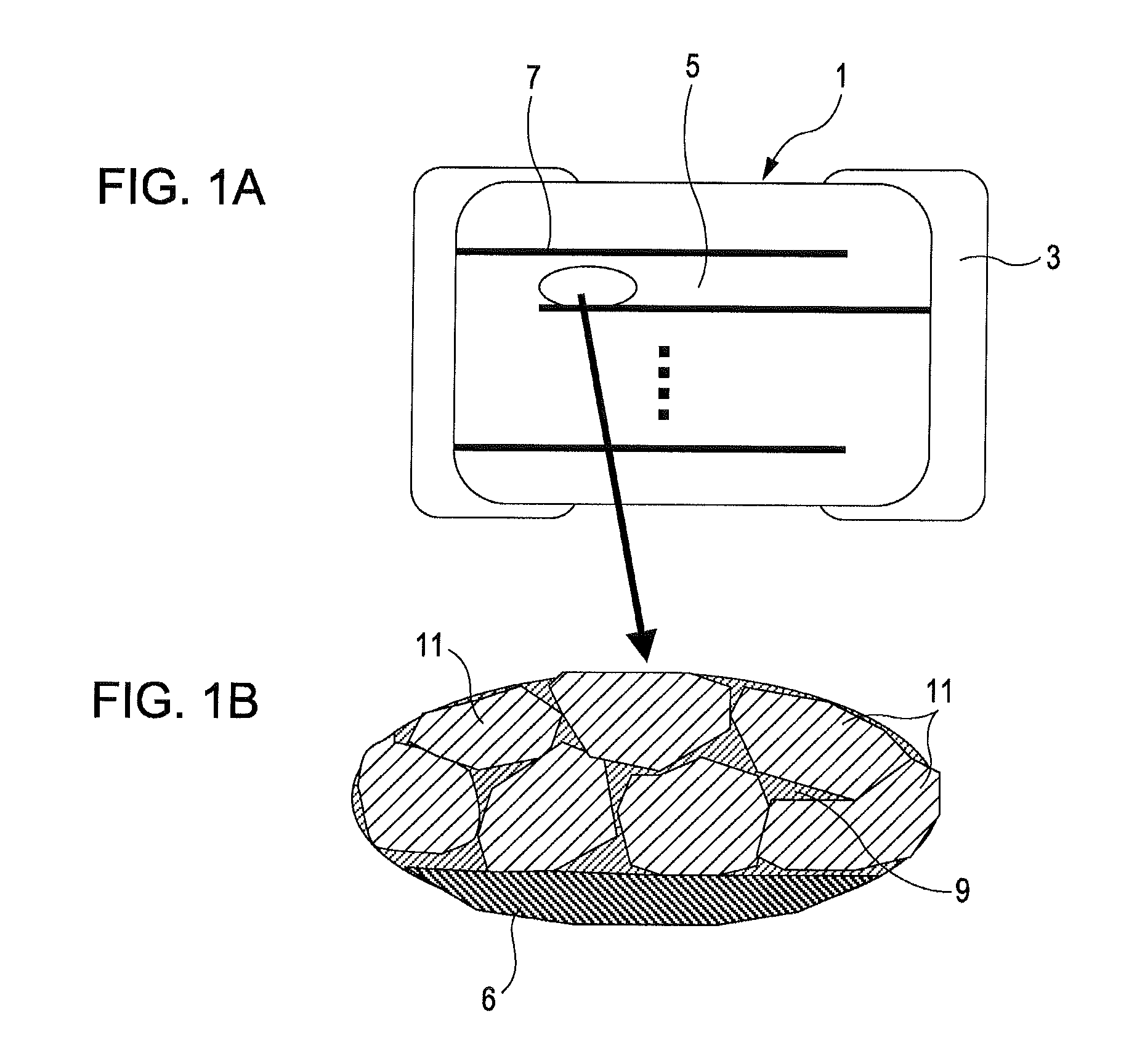
A multilayer ceramic capacitor includes a plurality of ceramic dielectric layers, a plurality of inner electrode layers and and external electrodes. The ceramic dielectric layers includes barium titanate crystal grains having pores inside. The inner electrode layers are between the ceramic dielectric layers. The external electrodes are electrically connected to the inner electrode layers. The barium titanate crystal grains each have a core-shell structure which include a core and a shell around the core. The the pores are mainly formed in the cores.

Description

[0001]The present application is a National Stage entry of PCT / JP2006 / 325613 filed on Dec. 22, 2006. Priority is also claimed to Japanese patent application 2005-37241 filed Dec. 26, 2005 and Japanese patent application 2006-085113 filed Mar. 27, 2006 under 35 U.S.C. § 119.BACKGROUND OF THE INVENTION[0002]1. Field of the Invention[0003]The present invention relates to multilayer ceramic capacitors and particularly to a multilayer ceramic capacitor including ceramic dielectric layers mainly composed of barium titanate crystal grains having pores therein.[0004]2. Description of the Related Art[0005]In recent years, size-reduction and higher capacitance are increasingly required for multilayer ceramic capacitors for use in small, high-performance electronic devices such as cellular phones. Therefore, reducing the thickness of and increasing the number of ceramic dielectric layers and internal electrodes to be stacked has been pursued. Such a multilayer ceramic capacitor includes cerami...

Claims


Application Information

Patent Timeline
Patent Type & Authority Patents(United States)
IPC IPC(8): H01G4/06
CPCC04B35/4682C04B35/62805C04B35/6281C04B35/62815H01G4/1227H01G4/30C04B2235/3206C04B2235/3208C04B2235/3224C04B2235/3225C04B2235/3262C04B2235/36C04B2235/365C04B2235/6582C04B2235/72C04B2235/762C04B2235/765C04B2235/766C04B2235/78C04B2235/79C04B2235/85C04B35/46H01G4/12
Inventor YAMAZAKI, YOUICHIMATSUBARA, KIYOSHISEKI, HIROMI
Owner KYOCERA CORP
Learn More