
Hybrid spread spectrum radio system

a radio system and spread spectrum technology, applied in the field of communications, can solve the problems of inability to reasonably obtain bandwidth, inability to meet the needs of users, etc., to achieve the effect of facilitating the need, facilitating the need, and facilitating the need

Inactive Publication Date: 2010-02-02
UT BATTELLE LLC
View PDF50 Cites 50 Cited by
  • Summary
  • Abstract
  • Description
  • Claims
  • Application Information

AI Technical Summary

Benefits of technology

[0041]Excellent signal security is another advantage of the invention: since so many signal parameters can change in a rapid fashion, and since successful synchronization requires substantial a priori knowledge of the code relationships between the DS, FH, TH, and polarization components of the HSS signal, the unintended listener will experience great difficulty in fully synchronizing with the HSS transmission and decoding the embedded data. An even higher level of HSS signal security can be achieved by dynamically altering the PN code relationships within the HSS transmitter; this can take the form of rolling code segments, scrambling of the code vectors, or table-based reassignments of the bit-pattern relationships. Obviously, the degree of difficulty in intercepting such a complex transmission without the required code “keys” or indices is extreme; of course, standard data-encryption techniques may also be added in addition to the above to provide even greater security of the transmitted data.
[0042]Still another major issue solved by the invention is that of efficient multiple access: in a proximal area, often dozens to hundreds or even thousands of devices (e.g., wireless sensor nodes, RFID tags, alarm units, and the like) are required to interoperate without significant data loss due to RF interference, multipath, or collisions from-other devices in the group. Appropriately programmed HSS can-exhibit superior multiple-access performance to even full power-controlled CDMA systems (e.g., cell phones) due to the concatenation of DS-CDMA techniques with the additional dimensions of the FH and TH modulations. These added signal dimensions permit greater diversity, access for more users, and / or can substantially ease the need for high accuracy in the CDMA power-control function. Moreover, the improved flexibility of the invention can support transmit-only devices which cannot be power-controlled and thus are not amenable to operating in a true CDMA-only environment. Since the multiple-access interference caused by the uncontrolled power levels of these units quickly exceeds tolerable limits for CDMA operation, especially with varying device locations (and, thus, the classic near-far problem for DS systems), the HSS protocol of the invention offers an effective means of accommodating such uncontrolled, randomly transmitting one-way units without adversely affecting the overall system multiple-access operations. This is principally accomplished by assigning specific CDMA codes to such devices and constraining their hopping frequency and time sequences to statistically avoid the more conventional (power-controlled) units' transmission slots.
[0043]In addition, to provide higher performance in typical multipath-prone industrial, military, and commercial wireless signal propagation environments, the capability to perform a continuous-phase (CP) synthesis of the combined DS / FFH signal waveform permits more effective utilization of RF spectrum (narrower bandwidth control and avoidance of transient spectral “splatter”) and simultaneously the potential for faster, more stable receiver synchronization in adverse transmission environments.
[0044]A further aspect of the invention is the application of statistically amplitude-dithered modulation and / or statistical polarization control of the combined CP-DS / FFH signal via pseudorandom-polynomial techniques to provide even more immunity to multipath-induced signal cancellations, which typically cause dropouts and accompanying high rates of data errors. The use of amplitude dithering minimizes the effect of successive chip cancellations due to closely spaced destructive signal reflections in low-loss (e.g., metal-walled) RF environments. It can be used to perturb or “break up” multipath-induced signal nulls where the signal is effectively cancelled by the destructive interferences due to unfortunate combinations of multiple reflected signals from diverse paths. When the vector sum of the multiple components approaches zero, by rapidly changing the amplitude of the transmitted signal (within the time-frame of the successively received reflection signals), the cancellation of the multiple-path signals can at least partially be “undone”, leaving a reasonable amount of instantaneous signal amplitude at the receiver to decode. To achieve maximum error-reduction benefit independently from this amplitude-dithering technique, the time rate of dithering (amplitude changing) should be at least comparable to the rate of arrival of successive reflected signals at the designated receiver (and ideally somewhat greater); this, in turn, still requires a fairly high dither rate unless combined with other aspects of the invention.
[0045]The application of PN-code controlled polarization control, when properly synchronized between transmitter and receiver(s), provides even greater signal diversity and, thus, immunity against multipath-induced signal nulls and dropouts (as well as unauthorized signal reception). This is accomplished by altering the transmitted signal wave polarization as a function of a specified PN code; with different orientations of the signal electric (E) and magnetic (H) fields, the respective reflection coefficients at room boundaries and other interfaces will also change, thus shifting (or “dithering”) the multipath null depths, frequencies, and locations. As will be described in later examples, the programming of the effective transmitted signal polarization can be accomplished by the concurrent control of the relative ratio of the power sent to two orthogonally polarized antennas, typically one vertical and the other horizontal.
[0046]Often the concatenation of some, most or all of the aforementioned methodologies will be required to provide a highly reliable link suitable for critical commercial, industrial and / or military applications in adverse (i.e., multipath- and interference-prone) RF environments. Although there are a multitude of possible specific board-level implementations of the hybrid spread-spectrum (HSS) modulator and / or demodulator, the most practical, compact, and cost-effective form is certainly that involving highly integrated custom integrated-circuit (IC) chip(s) to achieve the desired system functionality, programmability, size and reasonable power consumption characteristics at a usefully low cost.

Problems solved by technology

Conventional radio-frequency (RF) digital-data transmission schemes are in general highly susceptible to errors caused by multipath propagation and other interference conditions.
For OQPSK schemes as mentioned above, the minimum required bandwidth is halved but is still nevertheless very unwieldy in crowded RF bands.
Obviously, this bandwidth is not reasonably obtainable in any of the available Industrial, Scientific, and Medical (ISM) bands currently allocated for spread-spectrum transmission in the U.S. below 5 GHz (and would require the whole available 100-MHz band for ISM and Unlicensed National Information Infrastructure [U-NII] applications above 5 GHz), so other techniques must be applied to overcome the multipath problem for indoor wireless links.
However, either complex (and delay-inducing) interleaving and / or error-correction coding algorithms (e.g., Reed-Solomon) must be introduced into the link, or numerous packet retransmissions will be required to successfully transport the data payload.
In either case, significant levels of latency and concurrent link-rate limitations will inevitably result.
Furthermore, the use of “intelligent” hopping schemes which on average avoid certain hopping channels in a coordinated fashion have been historically disallowed by the Federal Communications Commission (FCC) on the ISM bands, since the average channel occupancy would be nonuniform and thereby skew the normal long-term random signal-frequency statistics intended for ISM-band frequency-hopping system operation, resulting in a statistical increase in interference to other users (although via rules changes by the FCC in the last few months, this prohibition has been somewhat relaxed).
Overall, however, this scheme, although usually workable for fixed devices, generally fails in mobile applications or when the RF environment is dynamic, since the positions of the multipath nulls (and thus the sets of “bad” channels) are constantly changing.
However, these methods have not hitherto been simultaneously employed in a programmably or adaptively coupled or coordinated fashion to provide a useful increase in the permissible number of devices operable in a given area for a specific amount of mutual interference.

Method used


Image

  • Hybrid spread spectrum radio system
  • Hybrid spread spectrum radio system
  • Hybrid spread spectrum radio system

Examples


example 1

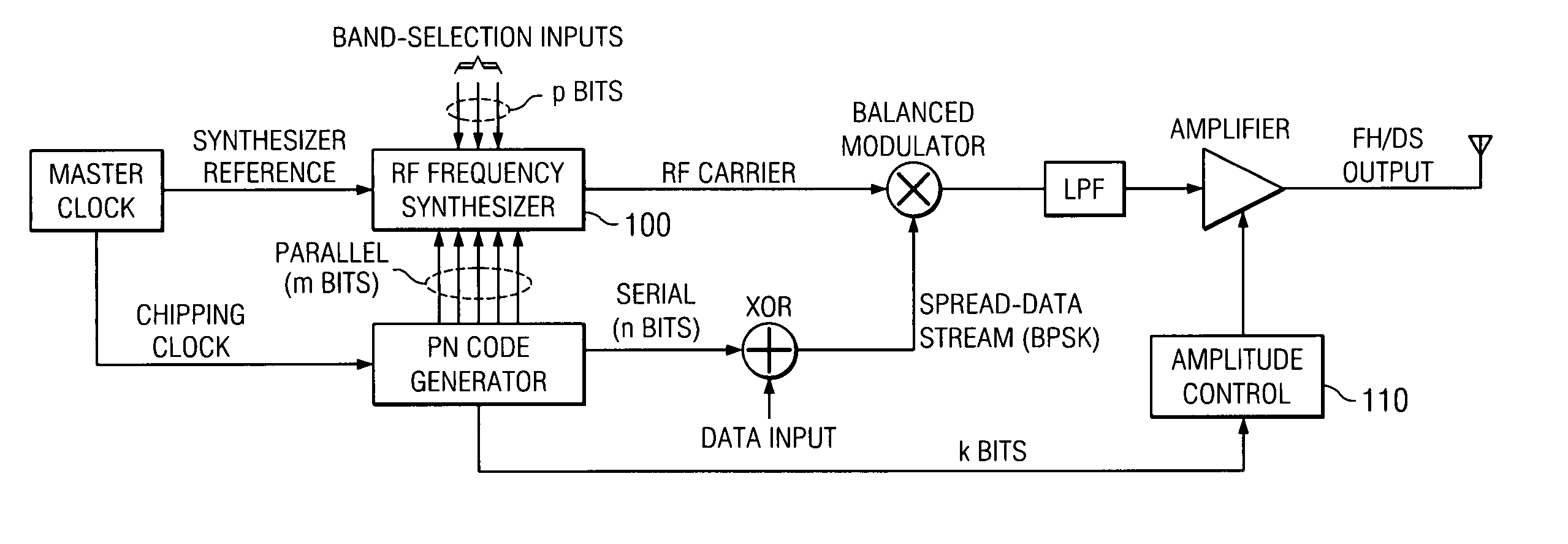
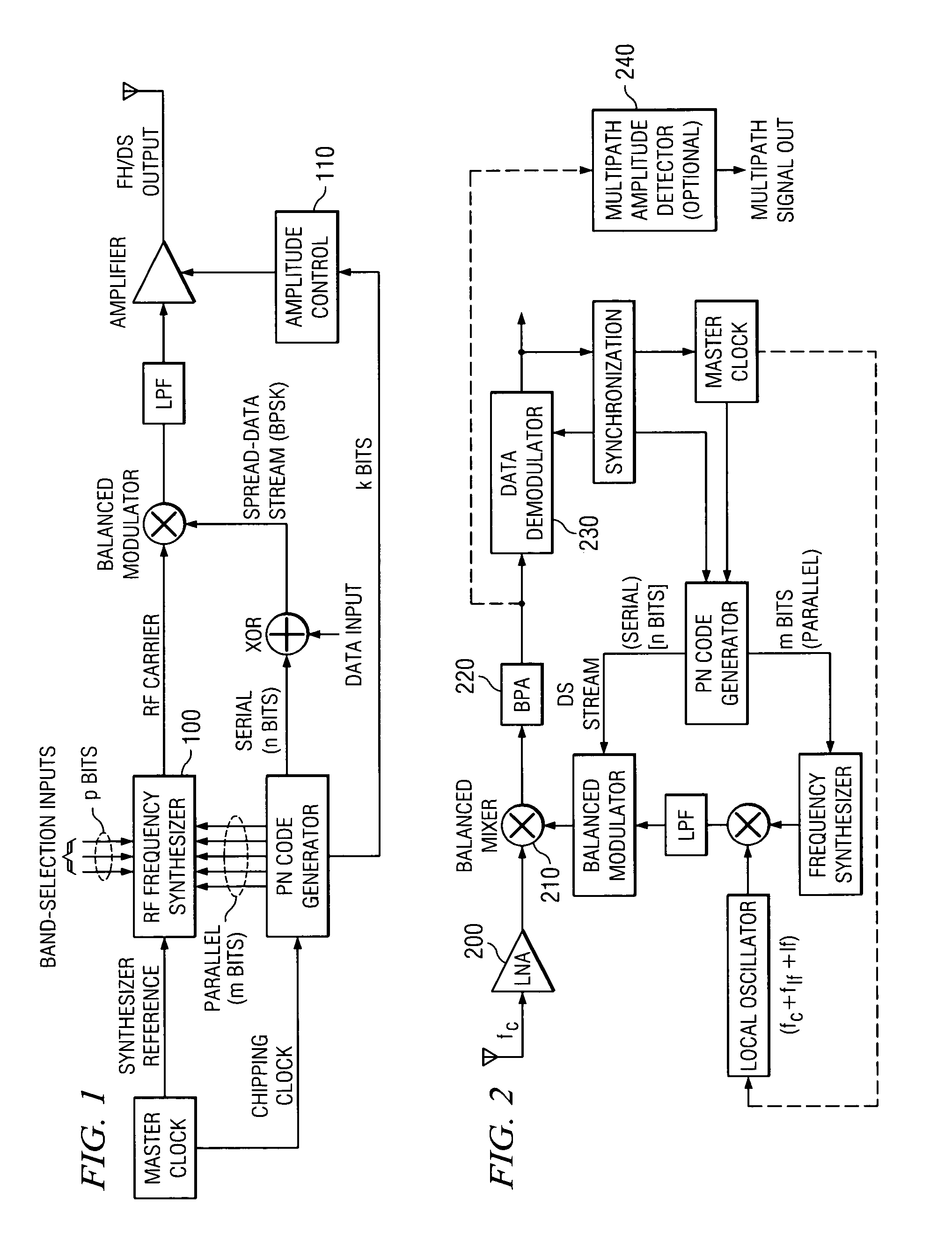
[0052]Referring to FIGS. 1-2, a hybrid frequency-hopping / direct-sequence (FH / DS) spread-spectrum scheme is depicted.

[0053]A hybrid frequency-hopping / direct-sequence (FH / DS) spread-spectrum transmitter depicted in FIG. 1 is configured for standard BPSK data modulation. A subset of m bits from the full n-bit (n>m) PN code is used in synchronization with the chipping sequence to drive an RF synthesizer 100 to generate the exact RF carrier frequency desired for the hybrid SS transmission. Note that an additional p higher-order bits in the RF synthesizer (DDS) frequency-control word are used to specify the RF operating band; the lower-order m bits from the PN register select the individual hopping channels. The precise mapping of hopping frequencies in the RF synthesizer 100 can be handled straightforwardly via a ROM map or within an FPGA or equivalent device. The latter-implementations are particularly useful when implementing fast frequency hopping or for very high data throughput and / ...

example 2

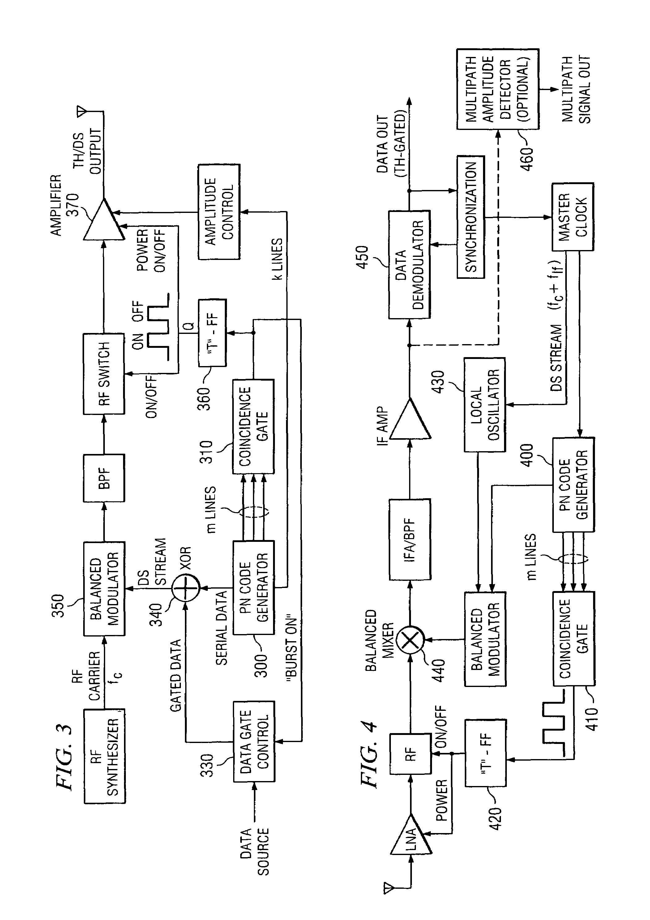
[0057]Referring to FIGS. 3-4, a hybrid time-hopping / direct-sequence (TH / DS) spread-spectrum scheme is depicted.

[0058]A hybrid time-hopping / direct-sequence (TH / DS) spread-spectrum transmitter is represented by FIG. 3. Here, as in the previous TH / DS transmitting scheme, the main PN code generator 300 of n bits also provides a subset of m bits to a pattern-detecting coincidence gate 310. When the selected m-bit pattern is recognized, a data-gate control unit 330 gates a burst of data bits into the DS spreader (via an exclusive-OR gate 340 feeding a balanced modulator 350). Simultaneously, a trigger (“T”) flip-flop 360, in essence driven by the coincidence output line, gates on a final RF power amplifier 370 for the prescribed interval (plus small power-up and power-down times) to complete the time-hopped burst transmission.

[0059]The corresponding hybrid TH / DS spread-spectrum receiver architecture is shown in FIG. 4. Here, the TH / DS receiver is similar to the FH / DS receiver unit describ...

example 3

[0060]Referring to FIGS. 5-6, a hybrid frequency-hopping / time-hopping / direct-sequence (FH / TH / DS) spread-spectrum scheme is depicted. The hybrid FH / TH / DS transmitter (FIG. 5) and receiver (FIG. 6) combine both FH / DS and TH / DS schemes to achieve more complex spreading distributions and afford even higher data security than the simpler types; the specific circuit details follow those in the previous diagrams.

[0061]These hybrid (FH / TH / DS) types of systems are probably the most useful for practical burst-mode wireless-sensor devices for difficult industrial RF environments. Alternatively, the bursts may be timed in a periodic rather than pseudorandom manner (thus, obviously, eliminating the true TH modulation component) when system update rates need to be highly regular, or when standard periodic time-slotting is desired.

[0062]Although these depicted transmitter implementations employ final RF carrier-frequency data-modulation methods, IF-modulation may alternatively be efficiently utili...


PUM


Abstract

Systems and methods are described for hybrid spread spectrum radio systems. A method includes modulating a signal by utilizing a subset of bits from a pseudo-random code generator to control an amplification circuit that provides a gain to the signal. Another method includes: modulating a signal by utilizing a subset of bits from a pseudo-random code generator to control a fast hopping frequency synthesizer; and fast frequency hopping the signal with the fast hopping frequency synthesizer, wherein multiple frequency hops occur within a single data-bit time.

Description

STATEMENT AS TO RIGHTS TO INVENTIONS MADE UNDER FEDERALLY-SPONSORED RESEARCH AND DEVELOPMENT[0001]The United States Government has rights in this invention pursuant to Contract No. DE-AC05-00OR22725 between the United States Department of Energy and UT-Battelle, LLC.BACKGROUND OF THE INVENTION[0002]1. Field of the Invention[0003]The invention relates generally to the field of communications. More particularly, the invention relates to spread-spectrum communications.[0004]2. Discussion of the Related Art[0005]Conventional radio-frequency (RF) digital-data transmission schemes are in general highly susceptible to errors caused by multipath propagation and other interference conditions. Historically, direct-sequence spread-spectrum techniques have offered reasonably good immunity against long-path (e.g. outdoor) types of reflections, where the time distribution (dispersion) of the arrival of the individual successive signal reflections is generally greater than the effective chipping p...

Claims


Application Information

Patent Timeline
Patent Type & Authority Patents(United States)
IPC IPC(8): H04B1/707H04B1/713H04B1/69
CPCH04B1/692H04B1/707H04B1/713
Inventor SMITH, STEPHEN F.DRESS, WILLIAM B.
Owner UT BATTELLE LLC
Learn More