Balloon expandable superelastic stent

a superelastic stent, balloon technology, applied in the field of balloon expandable superelastic stents, can solve the problems of difficult use of superelastic stents in blood vessel systems such as coronary systems, insufficient positioning, and inability to achieve the desired positioning, etc., to achieve the effect of convenient placement not only

Inactive Publication Date: 2010-02-09
TOKIN CORP
View PDF20 Cites 8 Cited by
  • Summary
  • Abstract
  • Description
  • Claims
  • Application Information

AI Technical Summary

Benefits of technology

[0015]It is therefore an object of this invention to provide a stent which can easily be placed not only in a blood vessel but also in a lumen of a human body or an animal.

Problems solved by technology

As well as the above-mentioned characteristics, the superelastic stent has several problems.
For example, its own spring function may damage the blood vessel wall and its autonomous shape recovery may cause a positioning error in the lumen.
Therefore, it is difficult to use the superelastic stent in a blood vessel system such as a coronary system.
However, use of such material is disadvantageous in that a force urging a lumen wall outward is weak to cause a positioning error following blood vessel pulsation.
This stent exhibits superelasticity at the living body temperature after it is released from the catheter but does not sufficiently achieve desired positioning of the stent as required in PTCA.
Therefore, depending upon a slot shape, sufficient deformation is difficult and sufficient effect is not obtained.

Method used


Image

  • Balloon expandable superelastic stent
  • Balloon expandable superelastic stent

Examples


first embodiment

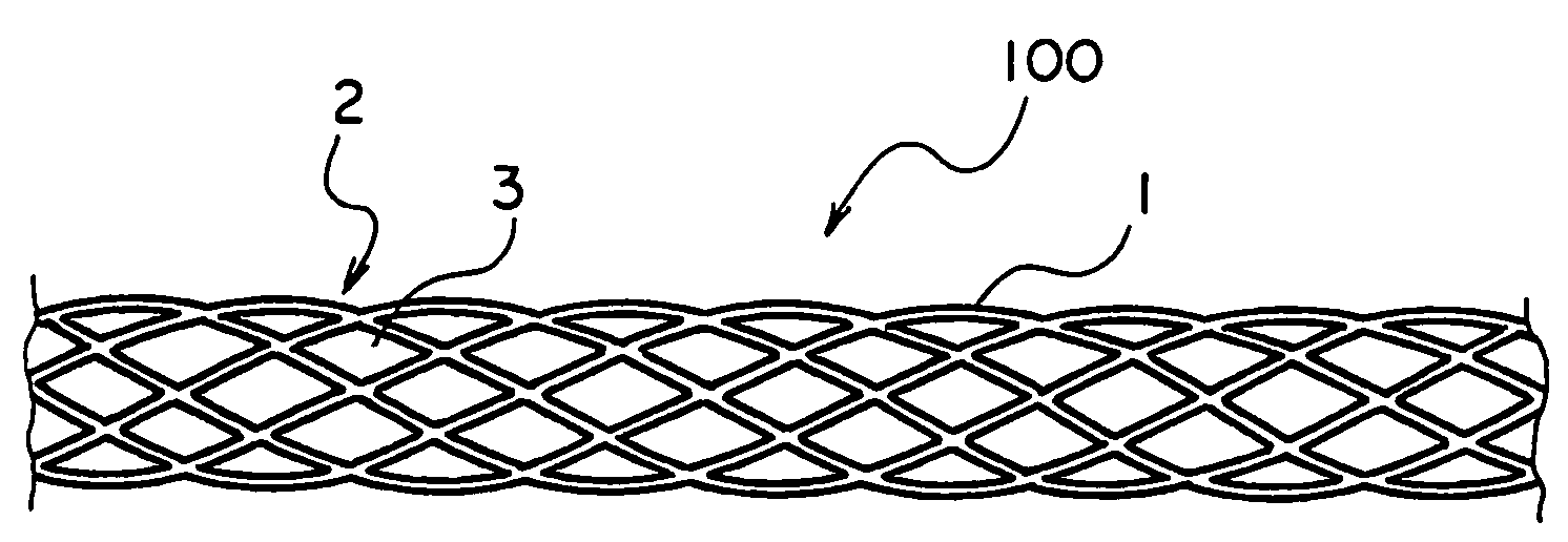
[0035]Each of tubes of φ5.0 mm of the Nos. 3 and 4 alloys was processed into a slotted shape illustrated in FIG. 1 by laser machining to obtain a stent 100 of a The stent 100 has a shape as a mesh tube 2 formed by a mesh wire 1 having slots 3. The stent 100 was subjected to shape memory treatment. The stent 100 having the shape as the mesh tube 2 was mechanically expanded radially in a dry-ice / alcohol bath at −50° C. into φ5.5 mm (ε=10%) and φ5.75 mm (ε=15%) as illustrated in FIG. 2. Then, the recovery temperature was examined. The result is shown in Table 2. Each tube thus expanded exhibited a temperature characteristic substantially similar to the test result of the above-mentioned wire material. It is therefore understood that, also in the shape of the stent, elevation of the shape recovery temperature by imposing the strain is achieved in the manner similar to the wire material.

second embodiment

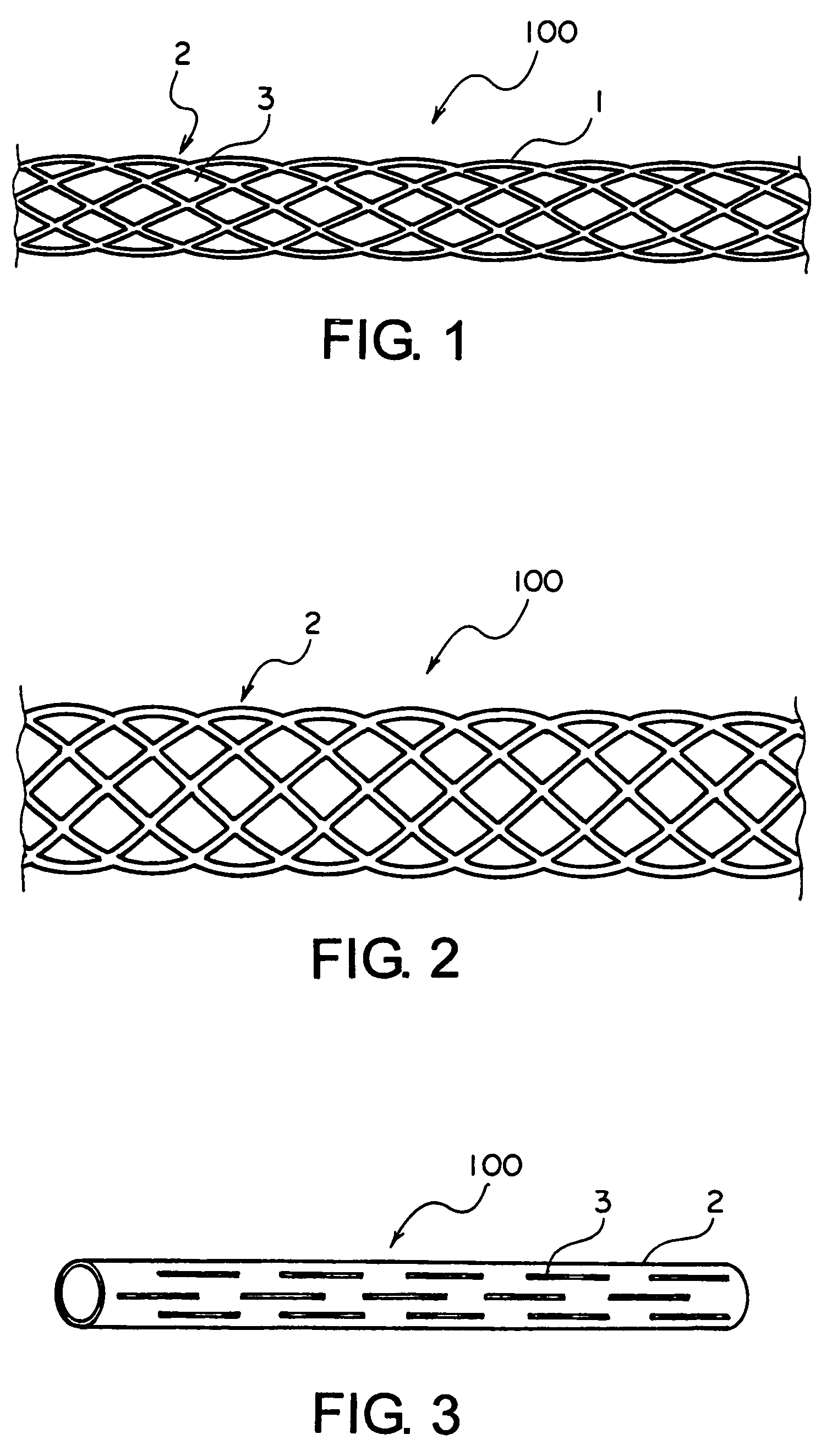
[0036]Next, as the stent 100 of a second embodiment, the tube 2 of φ1.2 mm of the No. 4 alloy was provided with the slots 3 in a staggered fashion in a longitudinal direction and in a circumferential direction, as illustrated in FIG. 3. Thereafter, the tube 2 was radially expanded into φ5.0 mm to obtain a mesh tube and subjected to shape memory treatment at 600° C. Then, the tube2 was radially contracted into φ1.2 mm and subjected to swaging into φ1.05 mm (the strain of about 13%). This tube had a shape recovery temperature of 55° C. Thus, an appropriateness of such strain imposing technique was confirmed.

[0037]Further, the slotted tube of φ1.2 mm of the No. 4 alloy in FIG. 3 was radially expanded into φ5.5 mm and subjected to heat treatment. Thereafter, the tube was radially contracted into φ1.2 mm again (the maximum strain of a slot angle was about 10%). The shape recovery temperature was examined and was about 40° C.

[0038]

TABLE 2expandedshape recovery behaviordiametershape recove...


PUM

PropertyMeasurementUnit
elongation strainaaaaaaaaaa
temperatureaaaaaaaaaa
elongation strainaaaaaaaaaa

Abstract

A balloon expandable superelastic stent is made of a Ti—Ni—Nb (the content of Nb being at least 3 at %) shape memory alloy. A shape recovery temperature of the stent is lower than a living body temperature in an unloaded state after shape memory treatment. The shape recovery temperature exceeds the living body temperature after the stent is mounted to a catheter and released from the catheter in a living body.

Description

[0001]This application claims priority to prior Japanese patent application JP 2004-62664, the disclosure of which is incorporated herein by reference.BACKGROUND OF THE INVENTION[0002]This invention relates to a stent to be placed in a lumen of a human body or an animal.[0003]As well known, a shape memory alloy, such as a Ti—Ni alloy, exhibits a remarkable shape memory effect in association with martensitic reverse transformation. It is also well known that the shape memory alloy exhibits excellent superelasticity or pseudoelasticity in association with stress-induced martensitic transformation caused by strong deformation in a parent phase, that is, austenite phase after the reverse transformation. The superelasticity is observed in a number of shape memory alloys. Among others, the superelasticity is remarkable in the Ti—Ni alloy and a Ti—Ni—X alloy (X═V, Cr, Co, Nb, or the like) obtained by substituting an element X for a part of the Ti—Ni alloy.[0004]The shape memory effect of t...

Claims


Application Information

Patent Timeline
Patent Type & Authority Patents(United States)
IPC IPC(8): A61F2/06A61F2/00A61F2/86A61F2/91A61L27/06A61L31/02A61M29/02
CPCA61F2/91A61F2/915A61L31/022A61F2002/91541A61F2002/91558A61F2210/0019A61L2400/16B65G21/10
Inventor YAMAUCHI, KIYOSHIMORI, KOUJIYAMASHITA, SHUZOU
Owner TOKIN CORP
Why Eureka
Try Eureka