Method of preparing patterned carbon nanotube array and patterned carbon nanotube array prepared thereby

a carbon nanotube array and patterned technology, applied in the direction of carbonsing rags, discharge tubes/lamp details, nanoinformatics, etc., can solve the problems of poor adhesion or electrical conductivity, the ito filled system cannot match the electrical conductivity of a continuous ito film, and the expected adverse effect on the control of conductive properties

Inactive Publication Date: 2010-02-16
SAMSUNG ELECTRONICS CO LTD
View PDF8 Cites 81 Cited by
  • Summary
  • Abstract
  • Description
  • Claims
  • Application Information

AI Technical Summary

Benefits of technology

[0016]An exemplary embodiment provides a method of preparing a patterned CNT array, which can form a uniform pattern and can prepare a patterned CNT array through a continuous process even without the use of a complicated photoresist process.
[0017]An exemplary embodiment provides a patterned CNT array, which has improved array uniformity and transmittance.
[0018]Exemplary embodiments provide a transparent electrode including the patterned CNT array, which may be easily prepared and has high transmittance, and various electronic devices incorporating it.
[0021]An exemplary embodiment may further include repeatedly alternating the arranging templates having CNTs, in a predetermined pattern on the exposed CNTs and selectively removing the templates arranged in the predetermined pattern thereby forming multiple layers of the exposed carbon nanotubes, such that a patterned CNT array may be multilayered. Since it is possible to obtain a patterned CNT array having relative high pattern uniformity, a conductivity and degree of integration may be increased while transmittance is not significantly decreased.

Problems solved by technology

As such, the conductive metal oxide is applied through a sputtering process or a spray pyrolysis process, which is nevertheless disadvantageous because it is expensive and thus unsuitable for mass production.
In the case where the ITO transparent electrode is applied on the plastic substrate, it may be deformed due to the difference in coefficient of thermal expansion from the substrate, undesirably worsening adhesion or electrical conductivity.
For example, although techniques of suspending ITO particles in a polymer binder have been proposed, this ITO filled system cannot match the electrical conductivity of a continuous ITO film.
However, the presence of dopants is expected to have an adverse effect on control of the conductive properties, and may not be compatible with device miniaturization.
However, in the case where the pattern is formed using a photolithographic process, the patterning process is complicated and incurs a high cost.
Further, in the case where the pattern is formed using a general printing process, the pattern has limited precision and thus is difficult to use to form a fine pattern.
Consequently, when such CNTs 200 are applied to the transparent electrode 100 of a display or a photovoltaic device, problems occur in which the image quality of the display is deteriorated or the photovoltaic efficiency of the photovoltaic device is decreased.

Method used


Image

  • Method of preparing patterned carbon nanotube array and patterned carbon nanotube array prepared thereby
  • Method of preparing patterned carbon nanotube array and patterned carbon nanotube array prepared thereby
  • Method of preparing patterned carbon nanotube array and patterned carbon nanotube array prepared thereby

Examples


example

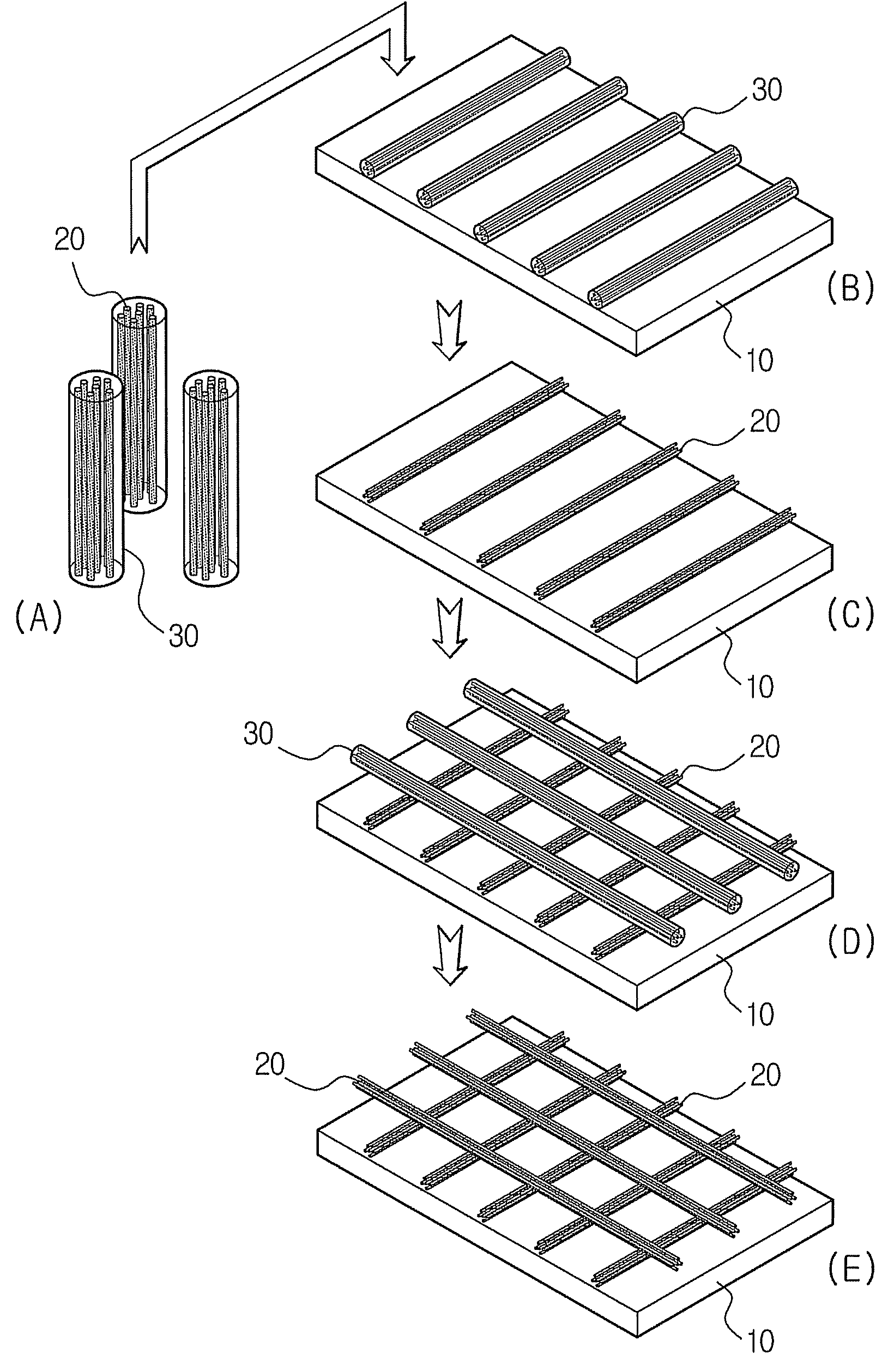
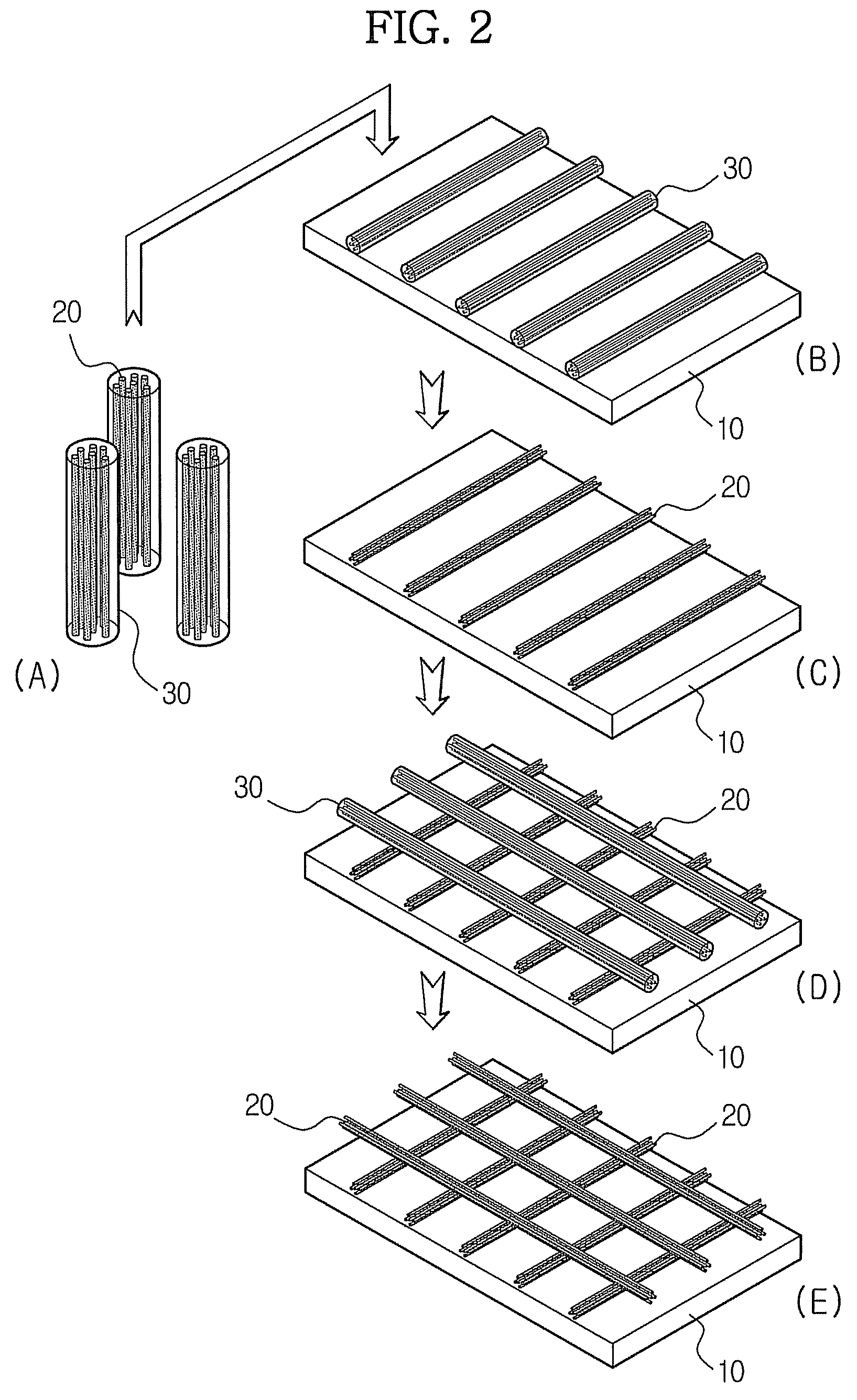
[0080]A CNT-dispersed chloroform solution was injected into the channels of porous templates in an amount the same as the volume of the porous channels using capillarity. The procedures of filling the channels with the CNTs using capillarity and then drying the solvent were repeated one or more times, depending on the desired CNT concentration.

[0081]The drying process was conducted in an oven at 150° C. for 6 hours or longer. A 0.2 wt % CNT / chloroform solution was supplied into the channels of silica porous templates having the volume of 1 cc / g. The supply and drying processes were repeated two times, after which the porous templates having the CNTs were arranged on a polycarbonate substrate.

[0082]Only the silica templates were selectively removed from the CNTs / templates arranged on the polymer substrate using a 5 wt % fluoric acid solution. On the polymer substrate having the CNTs arranged thereon, the arrangement of CNTs / templates and selective removal of templates were repeated.

[...


PUM

PropertyMeasurementUnit
lengthaaaaaaaaaa
diameteraaaaaaaaaa
diameteraaaaaaaaaa

Abstract

A method of preparing a patterned carbon nanotube array a patterned carbon nanotube array prepared thereby are provided. The method includes forming carbon nanotubes in channels of porous templates, arranging the templates in a predetermined pattern on a substrate and selectively removing the templates to expose the carbon nanotubes.

Description

[0001]This application claims priority to Korean Patent Application No. 10-2006-0047465 filed on May 26, 2006, and all the benefits accruing therefrom under 35 U.S.C. §119, the contents of which are herein incorporated by reference in its entirety.BACKGROUND OF THE INVENTION[0002]1. Field of the Invention[0003]The present invention relates, to a method of preparing a patterned carbon nanotube array and a patterned carbon nanotube array prepared thereby. More particularly, the present invention relates to a method of preparing a patterned carbon nanotube array in which carbon nanotubes (“CNTs”) are uniformly arranged using porous templates, to a patterned CNT array prepared thereby and to a transparent electrode including the patterned CNT array and thus having high light transmittance.[0004]2. Description of the Related Art[0005]In accordance with the rapid development of information and communication technologies and the requirement for visualization of various information data, th...

Claims


Application Information

Patent Timeline
Patent Type & Authority Patents(United States)
IPC IPC(8): H01J19/06
CPCB82Y10/00B82Y30/00D01F9/12H01J29/481Y10S977/742H01J2201/30469H01J2329/00B82B3/00B82B3/0061C01B32/168
Inventor CHOI, SEONG JAESEOL, KWANG SOOCHOI, JAE YOUNGYI, DONG KEEYOON, SEON MI
Owner SAMSUNG ELECTRONICS CO LTD
Why Eureka
Try Eureka