
Slope predictive control and digital PID control for a variable temperature control system

a technology of variable temperature control system and predictive control, which is applied in the field of control system, can solve problems such as error calculation between

Inactive Publication Date: 2010-03-02
AUTOMATED LOGIC CORP
View PDF22 Cites 10 Cited by
  • Summary
  • Abstract
  • Description
  • Claims
  • Application Information

AI Technical Summary

Benefits of technology

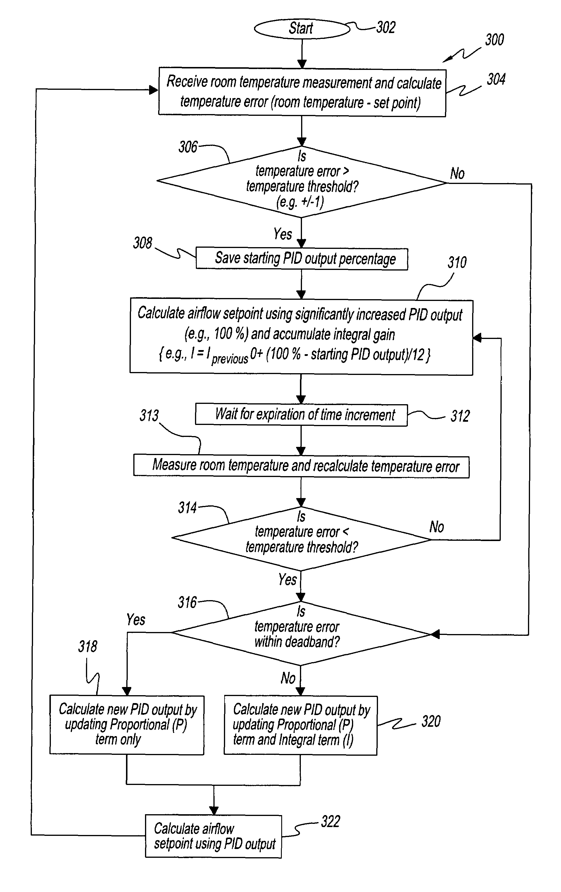
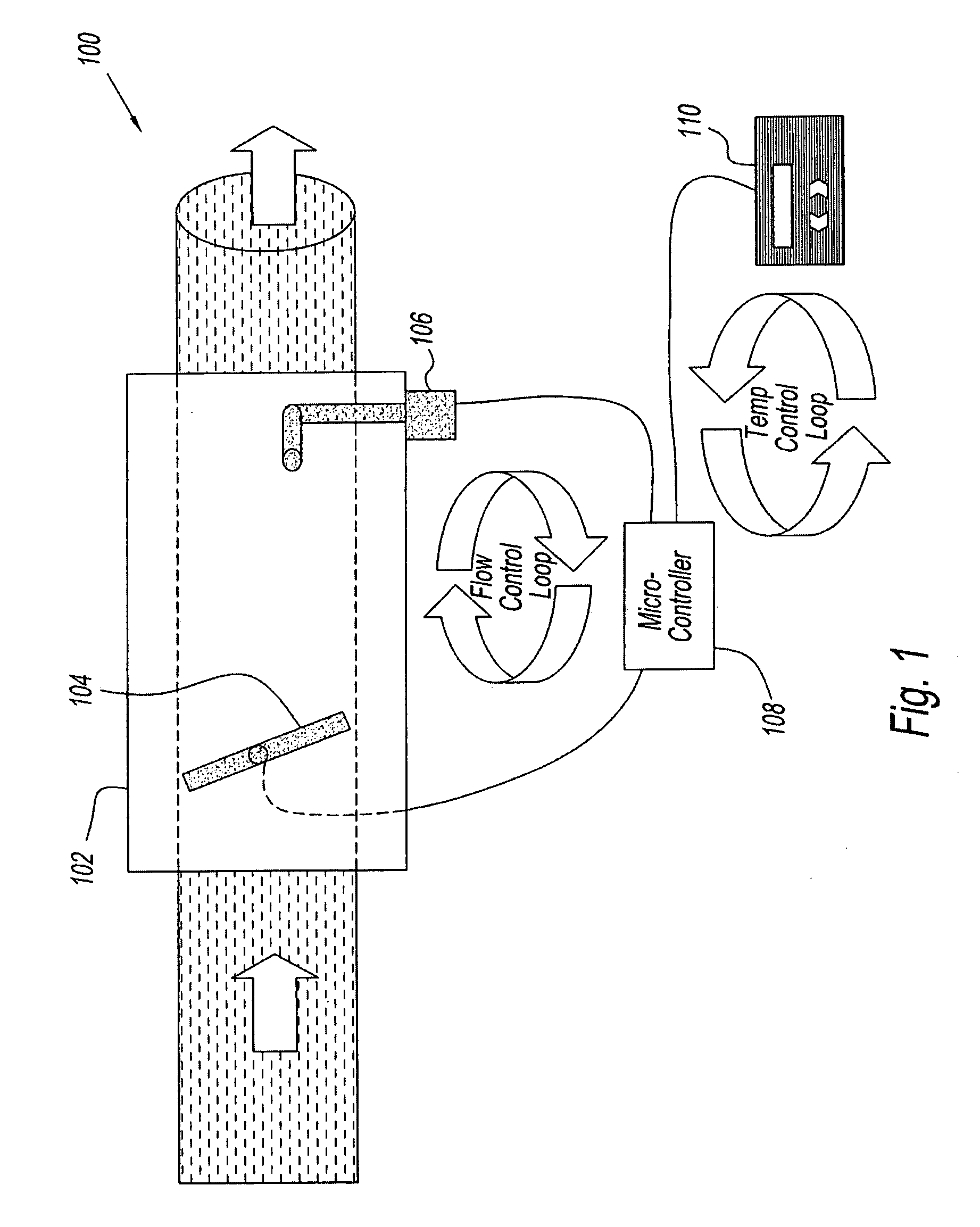
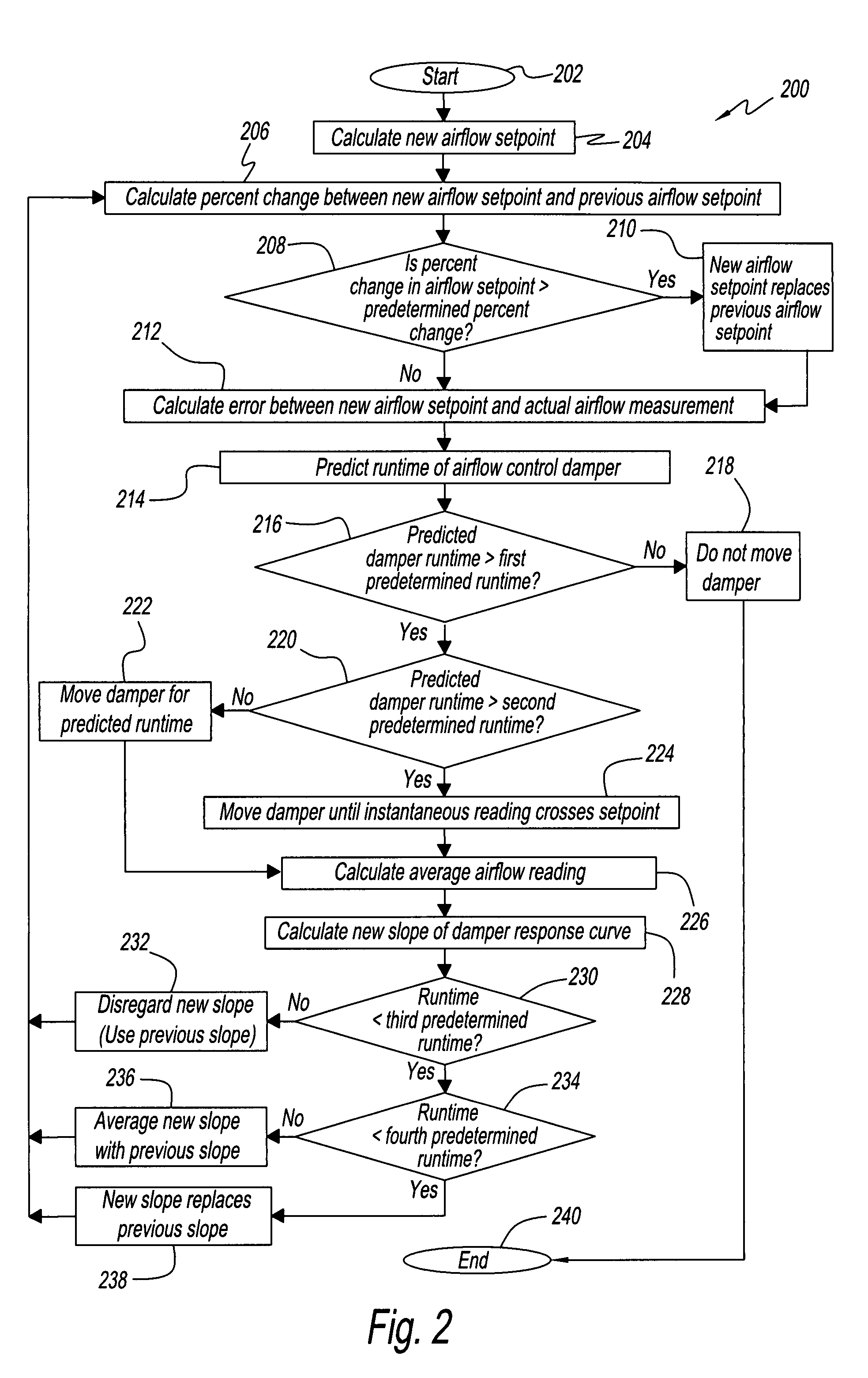
"The present invention provides an airflow control loop that uses averaged airflow measurements without the problems that are normally encountered with averaging measurements. This is accomplished through a predictive control scheme that measures the slope of the discharge temperature as a function of flow regulation device position and uses this slope to predict the position of the flow regulation device needed to achieve the desired discharge temperature. The invention also monitors the response of a Variable Temperature Control (VTC) over time and utilizes a self-learning algorithm to predict the response time of the system in order to determine when further control adjustments need to be taken. The invention includes a micro-controller for executing computer-executable instructions for receiving or calculating a temperature setpoint, typically based on a room temperature measurement from the room temperature sensor. The invention cycles through a number of steps until the time that a new room temperature measurement is received and a new temperature setpoint is calculated. The invention predicts a flow regulation device position adjustment in order to reach the temperature setpoint. The invention receives discharge air temperature measurements while generating the signal for actuating the flow regulation device the predicted position adjustment or until one of the discharge air temperature measurements is determined to have crossed the temperature setpoint. The invention calculates the average discharge air temperature and recalculates the error."

Problems solved by technology

A discharge air temperature measurement is also received and an error is calculated between the two temperature measurements.

Method used


Image

  • Slope predictive control and digital PID control for a variable temperature control system
  • Slope predictive control and digital PID control for a variable temperature control system
  • Slope predictive control and digital PID control for a variable temperature control system

Examples


Embodiment Construction

[0024]The present invention now will be described more fully hereinafter with reference to the accompanying drawings, in which preferred embodiments of the invention are shown. The present invention may be adapted for use in a wide variety of applications and is suitable for any temperature control system comprising a flow regulation device. By way of illustration and not by way of limitation, unless indicated otherwise, the preferred embodiment is presented in the context of a Variable Temperature Control (VTC) system, wherein the control flow device is a valve. The initial discussion, however, pertains to the application of the present invention to a Variable Air Volume (VAV) system, wherein the flow control device is a damper.

[0025]In one embodiment, the present invention provides flow and temperature control loops to accomplish a Variable Air Volume (VAV) temperature control algorithm in a manner that addresses the problems encountered in the control of prior art pressure indepe...


PUM


Abstract

The present invention applies a slope predictive control method to a Variable Temperature Control (VTC) system, measuring the slope of the discharge temperature as a function of flow regulation device position, and using this slope to predict the position of the flow regulation device needed to achieve the desired discharge temperature. The present invention also monitors the response of the VTC over time and utilizes a self-learning algorithm to predict the response time of the system in order to determine when further control adjustments need to be taken.

Description

RELATED APPLICATIONS[0001]The present application is a divisional application of U.S. application Ser. No. 10 / 804,278, filed Mar. 19, 2004, now U.S. Pat. No. 7,246,753 which is a continuation-in-part of U.S. application Ser. No. 10 / 425,136, filed Apr. 28, 2003, now U.S. Pat. No. 6,715,690, which is a continuation of U.S. application Ser. No. 09 / 850,422, filed May 7, 2001, now U.S. Pat. No. 6,554,198, the contents of all of which are incorporated herein in their entirety by reference.TECHNICAL FIELD[0002]The present invention relates generally to control systems. More particularly, the present invention relates to Variable Air Volume (VAV) and Variable Temperature Control (VTC) temperature control systems.BACKGROUND OF THE INVENTION[0003]Variable Air Volume (VAV) temperature control systems control the temperature within a room by modulating the amount of cool (or warm) air that is blown into the room by the heating and air conditioning system. A pressure dependent VAV temperature co...

Claims


Application Information

Patent Timeline
Patent Type & Authority Patents(United States)
IPC IPC(8): F24F7/00G05B13/02G05D7/00
CPCG05D23/19
Inventor HULL, GERRY GLANCYTOM, STEVEN TREECESAAR, RAYNOLD LEE
Owner AUTOMATED LOGIC CORP
Learn More