Display apparatus with circularly polarizing member and a resonator assembly for attenuating external light

a technology of resonator assembly and circular polarizing member, which is applied in the direction of discharge tube/lamp details, discharge tube luminescnet screens, electric discharge lamps, etc., can solve the problems of deteriorating the ability to prevent the reflection of external light, low contrast and visibility of display including organic el diodes, and the use of circular polarizing plates reduces the light-emitting efficiency of organic el diodes independently of display colors by half. , to

Inactive Publication Date: 2010-03-02
CANON KK
View PDF12 Cites 9 Cited by
  • Summary
  • Abstract
  • Description
  • Claims
  • Application Information

AI Technical Summary

Benefits of technology

[0011]The present invention provides a high-contrast display apparatus with high efficiency.
[0014]According to the present invention, a high-contrast display apparatus with high efficiency can be achieved.

Problems solved by technology

Therefore, there is a problem in that a display including the organic EL diode has low contrast and visibility.
This problem is not peculiar to organic EL displays but is common to light-emitting displays, such as quantum-dot light-emitting diode (QD-LED) displays, inorganic EL displays, and plasma displays, including reflective electrodes.
Therefore, there is a problem in that the use of such circularly polarizing plates reduces by half the light-emitting efficiency of organic EL diodes independently of display colors.
However, there is a problem in that if light-emitting efficiency is increased by increasing the spectral transmittance of a circularly polarizing member, the ability of preventing the reflection of external light is deteriorated because an increase in spectral transmittance reduces the degree of spectral polarization and the polarizing ability of the circularly polarizing member.

Method used


Image

  • Display apparatus with circularly polarizing member and a resonator assembly for attenuating external light
  • Display apparatus with circularly polarizing member and a resonator assembly for attenuating external light
  • Display apparatus with circularly polarizing member and a resonator assembly for attenuating external light

Examples


embodiments

[0110]Embodiments of the present invention will now be described. The present invention is not limited to the embodiments.

first embodiment

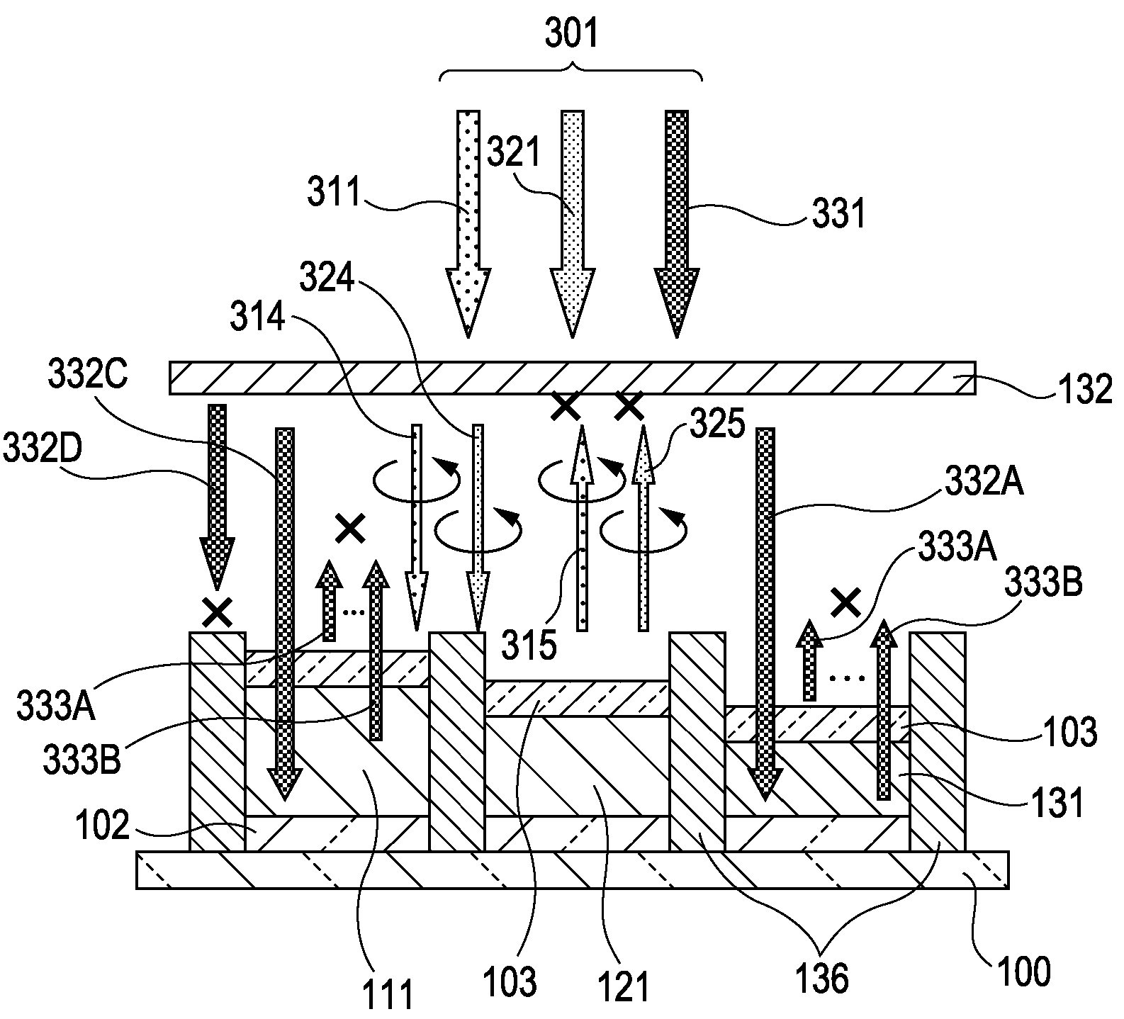
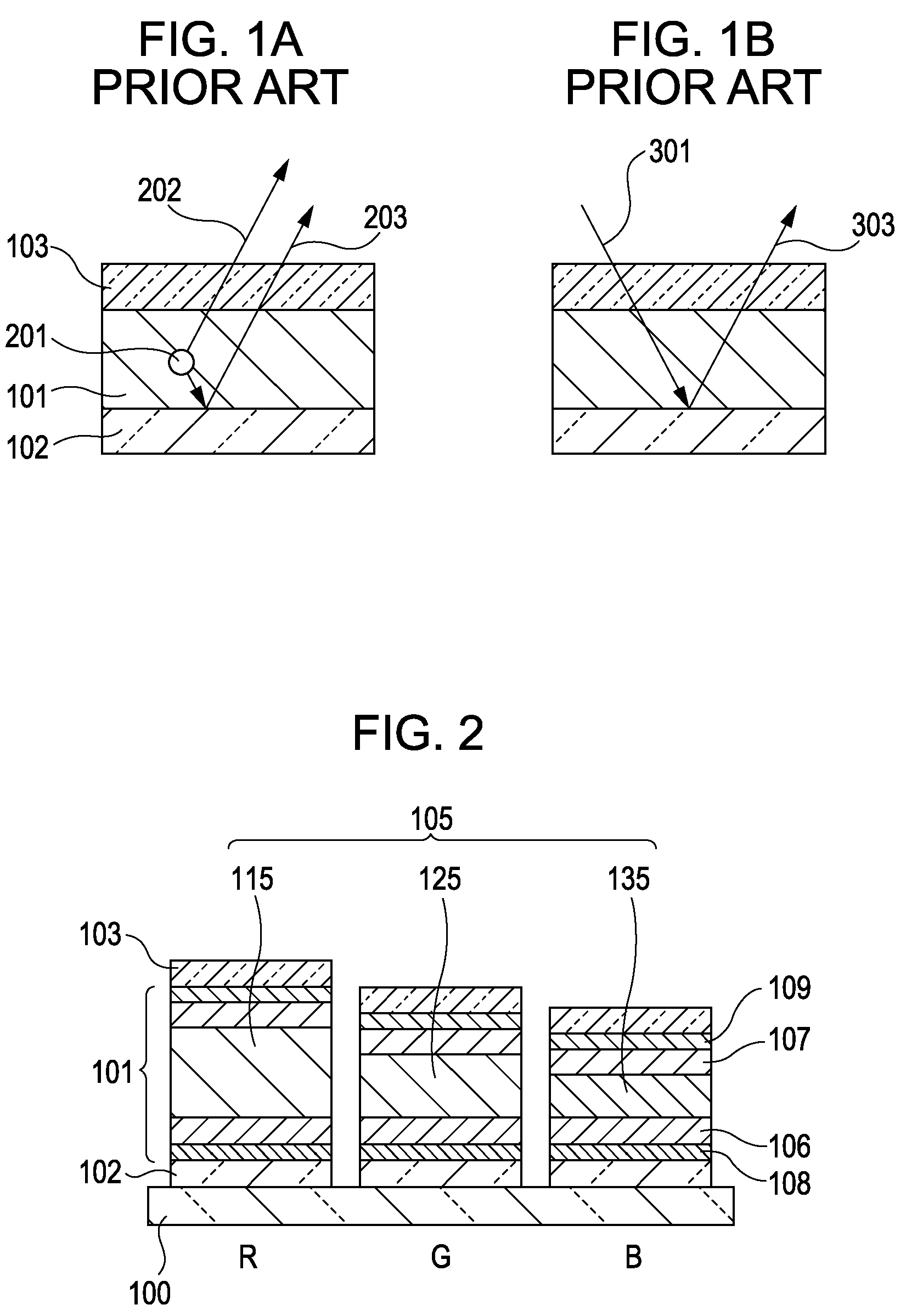
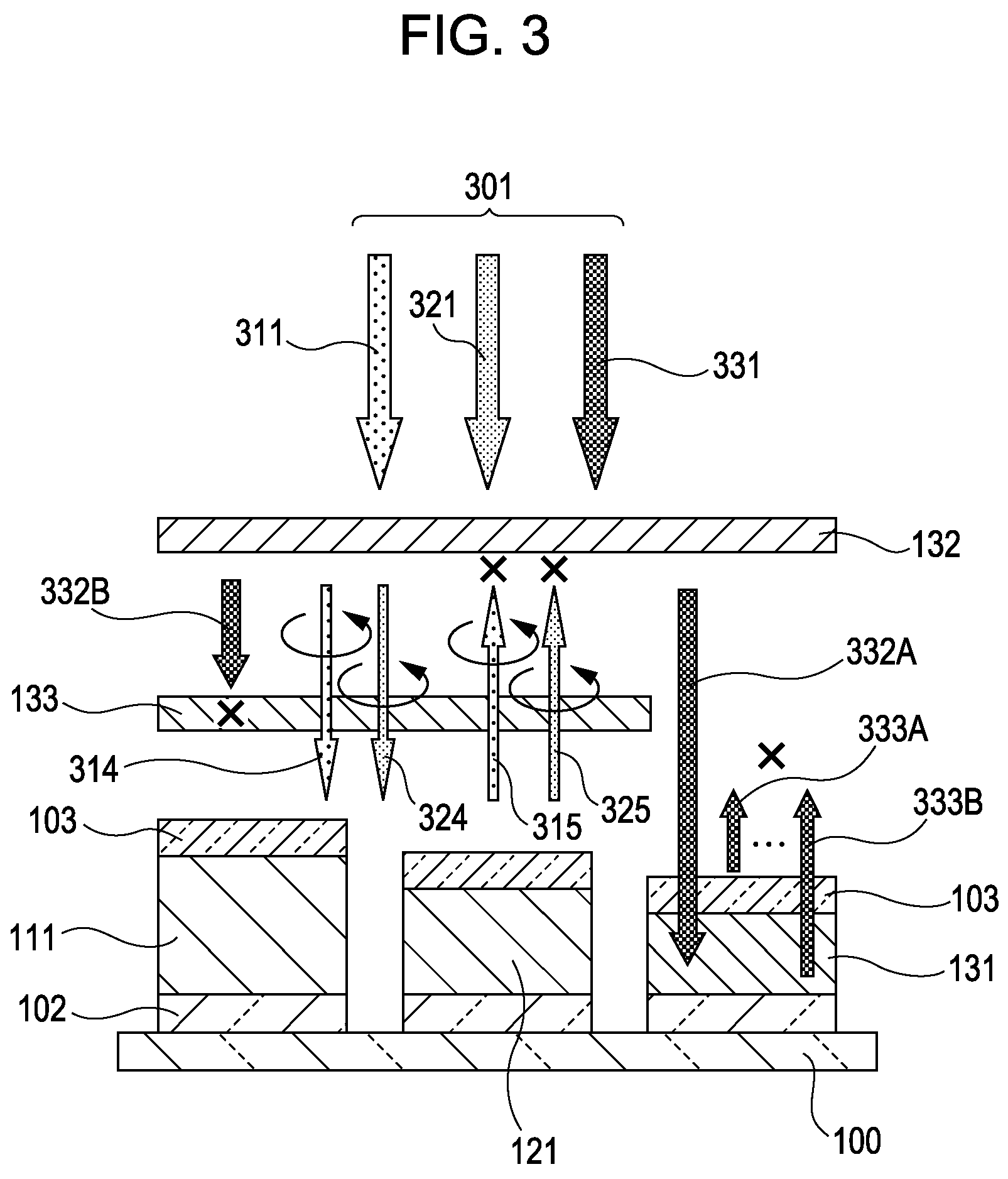
[0111]A full-color organic EL display apparatus having a configuration shown in FIG. 3 is manufactured by a method as described below.

[0112]A circuit for driving low-temperature polysilicon TFTs is formed above a glass base plate serving as a support and a planarization layer made of an acrylic resin is formed on the circuit, whereby a substrate is prepared. A layer of an Ag alloy (Ag—Pd—Cu) that is reflective is formed on the substrate by a sputtering process so as to have a thickness of about 100 nm and then patterned. An IZO layer for forming transparent conducting films is formed on the Ag alloy layer by a sputtering process so as to have a thickness of about 20 nm and then patterned, whereby reflective electrodes 102 are formed. Isolation layers made of an acrylic resin are formed between the reflective electrodes 102, whereby an anode-bearing substrate is prepared. The anode-bearing substrate is ultrasonically cleaned with isopropyl alcohol (IPA), subjected to boiling cleaning...

second embodiment

[0120]A display apparatus having a configuration shown in FIG. 13 is manufactured as described below. A circuit for driving low-temperature polysilicon TFTs is formed above a glass base plate serving as a support and a planarization layer made of an acrylic resin is formed on the circuit, whereby a substrate is prepared. A layer of an Ag alloy that is reflective is formed on the substrate by a sputtering process so as to have a thickness of about 100 nm and then patterned. An ITO layer for forming transparent conducting films is formed on the Ag alloy by a sputtering process so as to have a thickness of about 80 nm and then patterned, whereby reflective electrodes 102 are formed. Isolation layers made of an acrylic resin containing a red pigment are formed between the reflective electrodes 102 and then patterned, whereby an anode-bearing substrate including B-absorbing isolation layers 136 (non-emission regions) is prepared. The anode-bearing substrate is ultrasonically cleaned with...


PUM


Abstract

A display apparatus includes a substrate; a plurality of pixels arranged above the substrate, each including a plurality of sub-pixels emitting light of different colors; a circularly polarizing member disposed above the pixels, the transmittance of light of a selected color through the circularly polarizing member being higher than that of light of the other colors therethrough; and a light-absorbing member disposed only above the sub-pixels, emitting light of the non-selected colors. The light-absorbing member absorbs light of the selected color.

Description

BACKGROUND OF THE INVENTION[0001]1. Field of the Invention[0002]The present invention relates to display apparatuses including light-emitting devices and particularly relates to a display apparatus including organic electroluminescent (EL) diodes which emit light upon application of electric fields to thin films containing an organic compound.[0003]2. Description of the Related Art[0004]Organic EL diodes include anodes, cathodes, and thin films which contain fluorescent or phosphorescent organic compounds and which are sandwiched between the anodes and cathodes. The organic EL diodes emit light when electrons and holes are injected into the thin films from the cathodes and the anodes, respectively, and when the electrons are combined with the holes to generate excitons from the fluorescent or phosphorescent organic compound. The excitons transit from an excited state to a ground state and light is emitted. A study conducted by Eastman Kodak Company in 1987 reports on a diode having ...

Claims


Application Information

Patent Timeline
Patent Type & Authority Patents(United States)
IPC IPC(8): H01L51/52H01L51/50
CPCH01L51/5284H01L27/322H01L51/5265H10K59/38H10K50/852H10K50/865
Inventor FUKUDA, KOICHIISOBE, RYUICHIRO
Owner CANON KK
Why Eureka
Try Eureka