Device for small spot analysis using fiber optic interfaced spectrometers

Inactive Publication Date: 2010-03-02
MILOSEVIC MILAN +1
View PDF11 Cites 25 Cited by
  • Summary
  • Abstract
  • Description
  • Claims
  • Application Information

AI Technical Summary

Benefits of technology

[0016]When a sample is placed in the ellipsoid chamber mirror's other focal point, most of the radiation from the radiation source is refocused by the ellipsoid chamber mirror into a small spot (˜1 mm diameter) on the sample where it is diffusely reflected. The diffusely reflected radiation is collected and brought into an entrance aperture of an optical fiber by the ellipsoid collection mirror. This is done by placing the collection mirror inside the chamber mirror so that one of its focal points is on the sample and its other focal point on the entrance aperture of the optical fiber connected to a spectrometer. The portion of the radiation reflected off the sample that can be brought back to the spectrometer for analysis is limited by the numerical aperture of the fiber. Thus the collection mirror used to image the reflected radiation onto the optical fiber is sized to match the numerical aperture of the fiber. The entire remaining space above the sample not used by the collecting optics is utilized to bring incident radiation onto the sample thus maximizing the radiation energy brought to the spectrometer.
[0017]The area immediately above the sample is left unobstructed thus allowing the possibility of viewing of the sample. A lens can be incorporated into a cover placed

Problems solved by technology

This makes sampling spot selection difficult and hence the precise position of the sampled area is somewhat uncertain.
Another shortcoming of these probes is that they are subject to a numerical aperture restriction due to optical fibers that limits the amount of light that can be carried to and from the sample.
Also, their spectral range is

Method used


Image

  • Device for small spot analysis using fiber optic interfaced spectrometers
  • Device for small spot analysis using fiber optic interfaced spectrometers
  • Device for small spot analysis using fiber optic interfaced spectrometers

Examples


Embodiment Construction

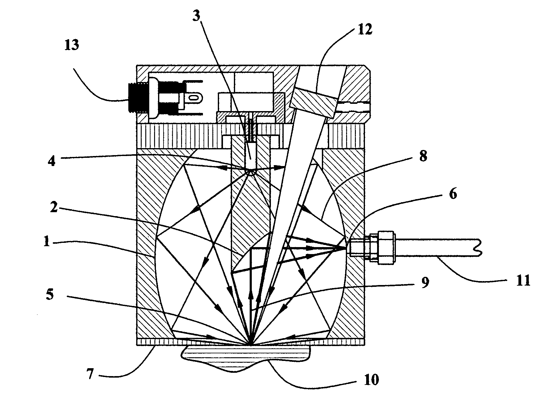
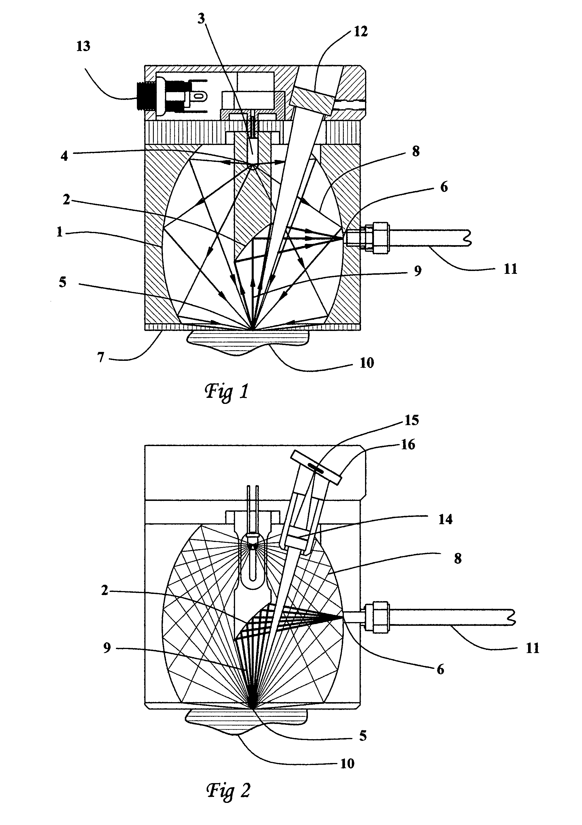
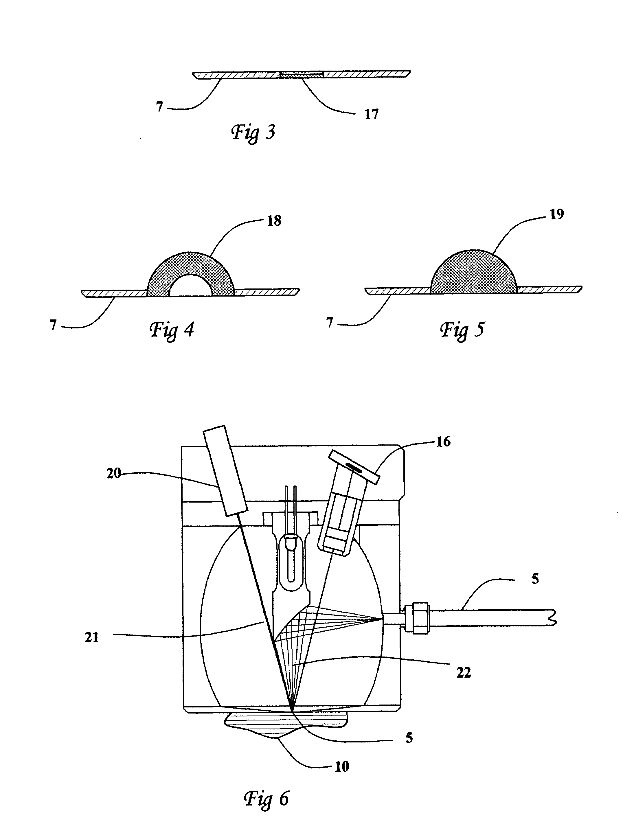
[0051]FIG. 1 illustrates one embodiment of the present invention. A source of electromagnetic radiation 3 (light bulb, LED, etc) is placed into one focal point 4 of the axially symmetric ellipsoid mirror 1. By the well-known property of ellipsoid mirrors, all light coming from one focal point of the mirror is relayed to the other focal point. This second focal point becomes the sampling spot 5 where a sample 10, having a diffusely reflecting surface, is introduced for measurement. A cover 7 could be placed on the bottom of the ellipsoid mirror 1 with a thickness such that the sampling spot 5 is in its lower surface. The cover 7 has an opening centered on the sampling spot 5 and of a size sufficient to allow the unobstructed illumination of the sample.

[0052]By resting the device on the flat sample 10 the surface of the sample is just in the right position for analysis. Incoming light exemplified by ray 8 reflects off the sample diffusely i.e. the angle at which the incoming ray of li...


PUM


Abstract

The present invention is an optical device for small spot analysis by diffuse reflectance using fiber optic interfaced spectrometers. The device comprises a source of electromagnetic radiation and a set of mirrors designed to project most of the radiation from the said source onto a less than 1 mm diameter spot on the sample, collect a portion of the radiation reflected by the sample and refocus this reflected radiation into an optical fiber. The said optical fiber then brings the said reflected radiation into a fiber optic interfaced spectrometer for spectral analysis. A means for the magnified viewing of the sample and the precise selection of the sampling spot for analysis is integrated into the invented device. Adding a digital camera and a laser module to the said device enables nearly simultaneous multimodal analysis of the same sampling spot by diffuse reflectance, Raman, and fluorescence spectroscopy and by image analysis.

Description

CROSS-REFERENCE TO RELATED APPLICATIONS[0001]This application claims the benefit of provisional patent application Ser. No. 60 / 781,767, filed 2006 Mar. 13 by the present inventors.FEDERALLY SPONSORED RESEARCH[0002]Not ApplicableSEQUENCE LISTING OR PROGRAM[0003]Not ApplicableBACKGROUND[0004]1. Field of Invention[0005]The field of the present invention relates to the multimodal analysis of a small spot on a sample by spectroscopy and sample image analysis. Specifically, it relates to the spectroscopic analysis of the sample using a fiber optic interfaced spectrometer.[0006]2. Prior Art[0007]There has always been an impetus to build spectrometric equipment that would bring radiation to the sample outside the sample compartment of a spectrometer. Dedicated analyzers were and still are being developed that integrate the functions of a spectrometer and a probe in a single package, for example U.S. Pat. No. 6,181,427 B1 (2001) issued to Yarussi, and U.S. Pat. No. 5,659,397A (1997) issued t...

Claims


Application Information

Patent Timeline
IPC IPC(8): G01J3/28
CPCG01N21/474G01N21/31G01N21/64G01N21/65G01N2201/0221
Inventor MILOSEVIC, MILANMILOSEVIC, VIOLET
Owner MILOSEVIC MILAN
Why Eureka
Try Eureka