[0008]The present invention, when properly made and used, provides a fluid-collection pan of sturdy construction that is configured and used in fluid collection and overflow prevention applications for long term support of a heavy unit or
system posing a fluid damage risk to its surroundings. It has an integrated
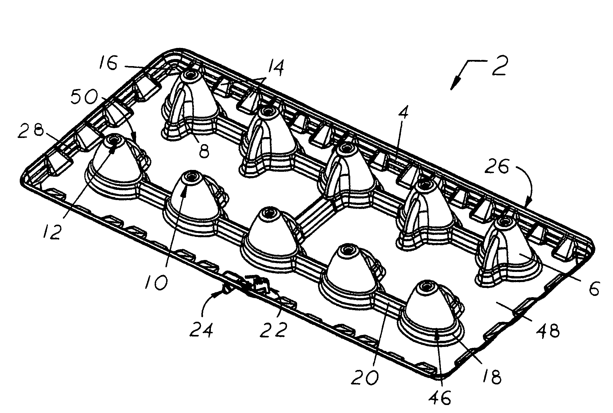
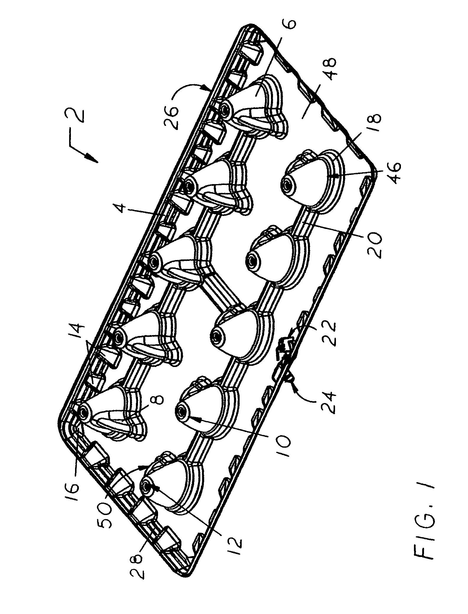
support system structured to provide enhanced material strength, with pan strength derived from its multiple raised egg-shaped supports that extend substantially across the length and width of the pan's bottom surface and pull plastic evenly during pan manufacture to avoid thin and weak areas. Pan strength is further derived from the elliptical base of each egg-shaped support that in combination with an upwardly-tapering protrusion creates a substantially triangular shape which broadens the
weight distribution of the supported fluid-causing unit across more of the pan's bottom surface, an optional annular
ridge around the elliptical base of each egg-shaped support and its associated protrusion, and optional stress-transmitting ribs extending between adjacent egg-shaped supports with positioning that does not impede fluid flow throughout the non-raised areas of the pan's interior bottom surface between the perimeter wall and the egg-shaped support. Further, non-raised areas in the pan are substantially level with one another so that collected fluid does not
pool in a
single area of the pan and potentially lead to bowing and / or buckling of that area, as well as perimeter wall lean-in and / or twisting of the pan. Thus also, excess fluid is not directed to the
float switch to cause premature shut-off of the supported fluid-causing unit or
pooling of fluid around the switch's float body that could transport debris to the float body, and / or promote
algae growth on it, both of which could seriously interfere with proper, reliable, and repeat float body deployment when needed for emergency shut off of the associated unit to prevent fluid damage to surroundings. Another
advantage of the present invention structural design that evenly pulls plastic during its manufacture, is that when uniform material thickness is achieved in a pan, a fluid-causing unit can be supported with less material thickness and manufacturing costs are reduced. In addition to enhanced material strength, the reduced incidence of pan material
cracking during pre-installation handling and use to support a fluid-causing unit provided by the egg-shaped supports reduces the need for post-installation inspection and maintenance of the pan and any associated
float switch. Further benefits of the egg-shaped structural design are enhanced safety and extended duration of present invention pan use over most prior art pans used in the same or similar applications.
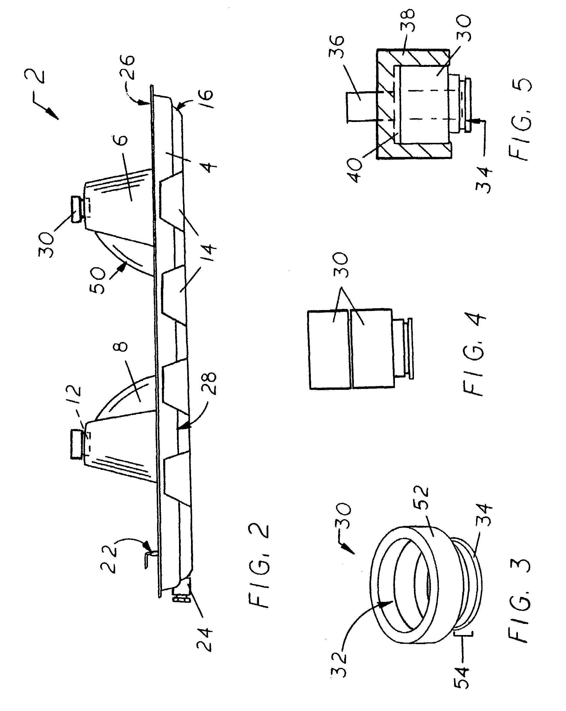
[0009]The egg-shaped supports each have a circular top surface that is transformed into an elliptical base as it meets the pan's bottom surface, and the upwardly-tapering protrusion typically associated with each egg-shaped support has a convexly-curved top edge that extends centrally from one of the longer sides of the elliptical base toward the support's top surface. The top surface of each egg-shaped support also has a central indentation configured for
receipt of at least one vibration
isolator, which collectively provide safety-enhancing contact between the egg-shaped support and the bottom surface of the supported fluid-causing unit for
weight distribution management that reduces the opportunity for movement of supported unit relative to the pan and thereby lessens the likelihood of premature pan collapse. Multiple vibration isolators in a vertically stacked array may be used to adjust the supported unit to an optimum working height, and when made from (or adapted with) non-combustible materials, vibration isolators can be used to meet non-combustible clearance requirements in furnace applications. Vibration isolators also provide reduced vibration and enhanced heat deflection around a supported fluid-causing unit. Egg-shaped supports are located substantially across the length and width of the pan's bottom surface. The egg-shaped supports are also large and sturdy, have a hollow upwardly-tapering interior that facilitates nesting of multiple stacked pans, have a top surface extending upwardly above the top of the perimeter wall, all have substantially the same height dimension, and they may be aligned into two longitudinally-extending rows that are off-set (non-centered) in positioning relative to the pan's bottom surface so as to locate the supports under the heaviest portions of a fluid-containing unit that is not evenly balanced in weight. The off-set positioning can also leave more room for easier installations, and space for positioning drain lines and gas lines. An annular
ridge around the egg-shaped supports and their upwardly-tapering protrusions helps to distribute the weight of the supported unit over a wider portion of the pan's bottom surface, and the convexly-curved perimeter configuration of the annular
ridge reduces the number of pressure points in the pan that could lead to
cracking and
premature failure. When stress-transmitting ribs are present between adjacent egg-shaped supports, the annular ridge around each egg-shaped support merges with near end of the rib extending toward it. Any angular-to-arcuate (or arcuate-to-angular) transition present between the ribs and the annular ridges is softened to reduce pressure points.
[0010]It is the structured design of the present invention pan, in addition to the
polycarbonate material from which it is substantially made, that together allow it to
resist cracking during installation, as well as bowing, bending, warping, buckling,
distortion, and collapse during extending time periods of use. Preferred materials include but are not limited to
polycarbonate,
polycarbonate alloys, polycarbonate blends, polycarbonate alloys and blends using ABS, polycarbonate alloys and blends using PBT, polycarbonate alloys and blends using PET, polycarbonate alloys and blends using PP, materials impervious to
corrosion,
impact resistant materials,
heat resistant materials, non-flammable materials, and materials substantially unaffected by large ambient temperature fluctuations. Resistance to UV
radiation is not necessarily a contemplated feature of the present invention, unless dictated by the application. Strengthening features may also be provided in the perimeter wall structure of the present invention pan, and may include any of the following, alone or in combination, staggered perimeter gussets, at least one horizontally-extending perimeter rib between gussets, angled corners, an up-turned perimeter lip, a mounting shelf configured for quick attachment of a shut-off switch, and a ribbed area configured for protecting the a float switch from
side impact directed toward the perimeter wall. Their configurations also help to reduce the number of pressure points in the pan that could lead to its premature cracking and / or failure. When a quick-mounting shelf is used in the present invention pan for attaching a float switch in fixed association with a drain line connection having a configuration complementary to the mounting shelf, rapid float switch installation is achieved and automatic leveling of the float body occurs when the pan is placed into a level orientation. Only a simple height adjustment of the deployable float switch body may additionally be required during installation, according to the quantities of fluid collection anticipated in an application and the depth of fluid considered safe in the particular application. Although the use of a quick-mounting shelf is not critical to the present invention pan, it is preferred for the many advantages it provides during float switch installation and use. An equally important use of the present invention pan is management of the routine cycles of
fluid accumulation and
evaporation expected to occur in it during the support of a fluid-causing system or unit that at least periodically produces condensate as a by-product of its operation, perhaps as a result of inadequate insulation, so that
pooling of collected fluid in a
single area of the pan is prevented to avoid bowing and / or buckling in that area and the potential for buckling and pan collapse.
[0011]The description herein provides preferred embodiments of the present invention but should not be construed as limiting its scope. For example, variations in the number, height dimension, and configuration of vibration isolators or other dampening inserts used in association with the egg-shaped supports' indentations; the material from which vibration isolators are made and whether they would be readily replaceable or fixed within the top indentation of an egg-shaped support; the number, width dimension,
depth dimension and configuration of the perimeter wall gussets used; whether all of the perimeter wall gussets would have a uniform width dimension or a horizontally-extending rib depending between adjacent gussets; the number of egg-shaped supports used; the height of the egg-shaped supports above the top of the perimeter wall; whether the egg-shaped supports are in rows that are centered or non-centered relative to the pan's bottom surface; and the presence of the quick-mounting shelf used for prompt connection of a drain line and float switch
assembly, other than those shown and described herein, may be incorporated into the present invention. Thus the scope of the present invention should be determined by the appended claims and their legal equivalents, rather than being limited to the examples given.

