
Systems and methods for use by an implantable medical device for evaluating ventricular dyssynchrony based on T-wave morphology

a medical device and ventricular dyssynchrony technology, applied in the field of implantable medical devices, can solve the problems of intraventricular dyssynchrony, increased severity of dyssynchrony, intraventricular dyssynchrony, etc., and achieve the effect of reducing dyssynchrony and simple procedur

Active Publication Date: 2010-03-09
PACESETTER INC
View PDF35 Cites 72 Cited by
  • Summary
  • Abstract
  • Description
  • Claims
  • Application Information

AI Technical Summary

Benefits of technology

[0013]Hence, the presence of two peaks or two troughs within the T-wave is an indication of at least some amount of ventricular dyssynchrony and also an indication of possible CHF. The time delay between the peaks or troughs can be measured as an indication of the relative severity of the dyssynchrony and the underlying CHF. That is, a larger time delay between peaks or troughs within the T-wave is indicative of a greater severity of dyssynchrony and CHF. Moreover, heart failure that is particularly severe can cause intraventricular dyssynchrony, as explained above, where different portions of a given ventricular chamber contract asynchronously. For example, portions of the LV myocardium near the apex of the LV may contract asynchronously with respect to portions of the LV that are closer to the SA node. Likewise, different portions of the RV may contract asynchronously with respect to other portions of the RV. As such, different portions of the LV and RV may also repolarize asynchronously, resulting in a T-wave that has three or more peaks. Hence, the total number of peaks or troughs can also be used to evaluate the relative severity of ventricular dyssynchrony and CHF. For devices equipped to perform biventricular pacing, the parameters used to control pacing can be automatically adjusted by the device so as to reduce the degree of dyssynchrony by reducing the number of T-wave peaks or troughs or, at least, reducing the time delay therebetween. For example, an interventricular (LV-RV) pacing delay and / or an AV pacing delay may be automatically adjusted.
[0015]In a third illustrative embodiment, the morphological feature of the T-wave that is exploited is the number of inflection points within the T-wave (i.e. the number of points wherein the second numerical derivative of the T-wave signals is zero). The detection of more than three points of inflection within individual T-waves is deemed to be indicative of ventricular dyssynchrony. As noted above, ventricular dyssynchrony can result in an increase in the number of peaks within the T-wave. As such, the number of points of inflection increases as well. A T-wave without ventricular dyssynchrony typically has only three points of inflection. If the T-wave splits into two, then, at least five points of inflection are typically detectable. Otherwise conventional numerical techniques may be used to detect and count the points of inflection. The use of points of inflection is particularly helpful if it is otherwise difficult to count the number of peaks within the T-wave, as may occur if the T-wave becomes fragmented into multiple peaks due to asynchronous contractions of different portions of the LV or different portions of the RV. The parameters used to control biventricular pacing can be automatically adjusted by the device so as to reduce the degree of dyssynchrony by reducing the number of points of inflection in the T-wave.
[0017]Other T-wave based morphological parameters may be exploited as well, either alone or in combination. In general, any T-wave parameter that is affected by ventricular dyssynchrony can potentially be used to evaluate ventricular dyssynchrony. For example, any parameter representative of the “fractionation” of the T-wave may potentially be exploited, such as a parameter representative of the frequency of the T-wave. (The number of peaks of the T-wave and the number of points of inflection are also generally representative of T-wave fractionation.) Multiple T-wave morphological parameters may be simultaneously exploited to provide a more robust evaluation of dyssynchrony. The morphology and timing of T-waves simultaneously recorded from the RV and LV can be compared to each other. Even if one of the ventricles is normal, not affected by intraventricular dyssynchrony, the relative timing of the fractionated or split T-wave of the other ventricle can indicate a level of interventricular dyssynchrony. Moreover, T-wave based parameters may be selectively combined with other parameters (such as QRS-complex parameters, pressure measurements, ER parameters, etc.) to provide a still more robust evaluation.
[0019]Thus, a computationally simple procedure for detecting ventricular dyssynchrony and for optimizing pacing parameters to reduce dyssynchrony is provided, which does not require the device to directly evaluate cardiac output or stroke volume or other cardiac performance parameters adversely affected by ventricular dyssynchrony. Preferably, adjustments to the pacing parameters are made substantially in real-time. Trends in ventricular dyssynchrony within the patient may also be identified and tracked to detect, for example, progression of CHF as evidenced, e.g., by an increasing fractionation of the T-wave. Appropriate warnings may be generated for the patient, the physician, or both.

Problems solved by technology

Intraventricular dyssynchrony manifests by significant delays in the depolarization or repolarization of various regions of a ventricle.
That is, a larger time delay between peaks or troughs within the T-wave is indicative of a greater severity of dyssynchrony and CHF.
Moreover, heart failure that is particularly severe can cause intraventricular dyssynchrony, as explained above, where different portions of a given ventricular chamber contract asynchronously.

Method used


Image

  • Systems and methods for use by an implantable medical device for evaluating ventricular dyssynchrony based on T-wave morphology
  • Systems and methods for use by an implantable medical device for evaluating ventricular dyssynchrony based on T-wave morphology
  • Systems and methods for use by an implantable medical device for evaluating ventricular dyssynchrony based on T-wave morphology

Examples


Embodiment Construction

[0035]The following description includes the best mode presently contemplated for practicing the invention. This description is not to be taken in a limiting sense but is made merely to describe general principles of the invention. The scope of the invention should be ascertained with reference to the issued claims. In the description of the invention that follows, like numerals or reference designators are used to refer to like parts or elements throughout.

Overview of Implantable Medical System

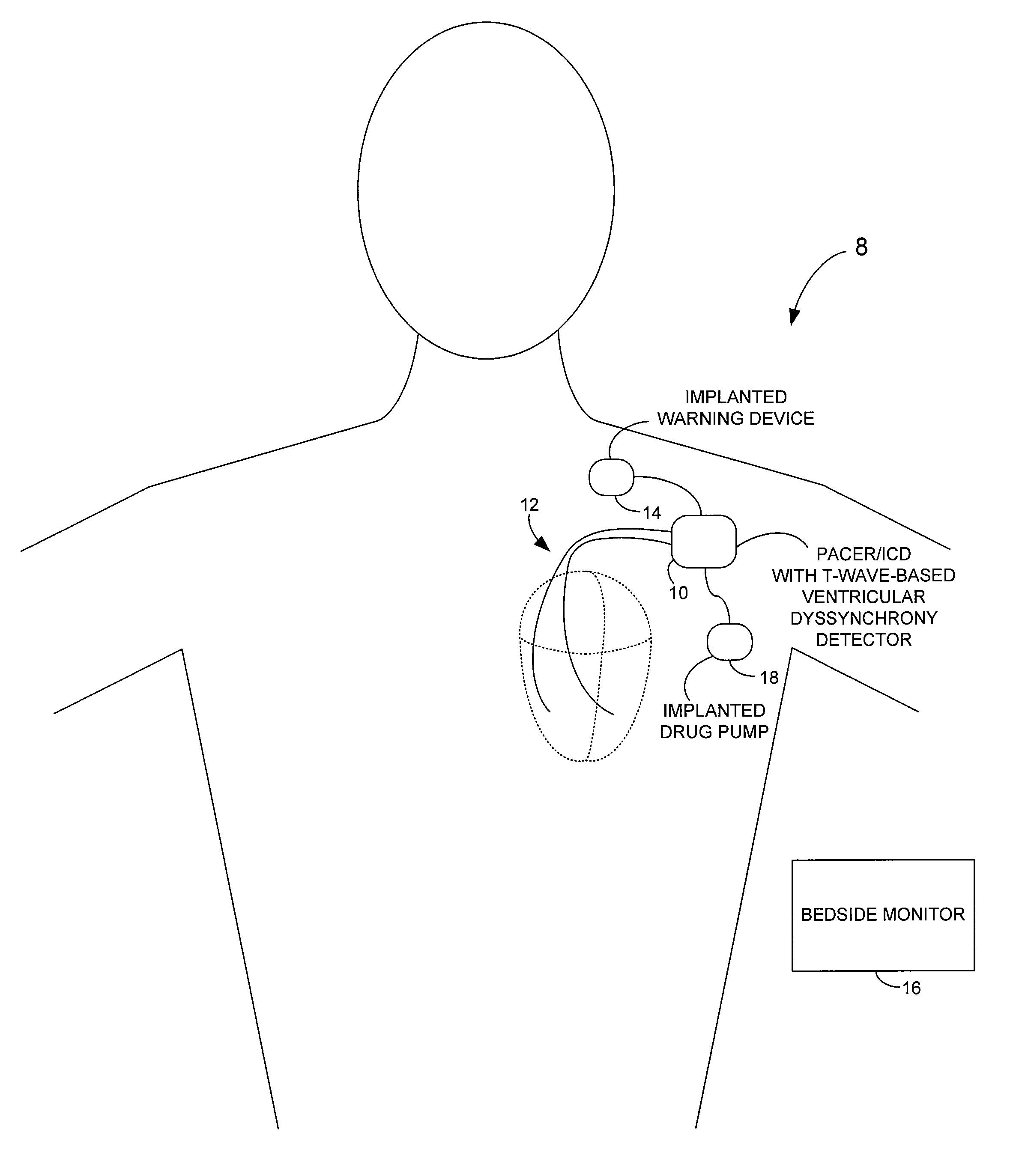
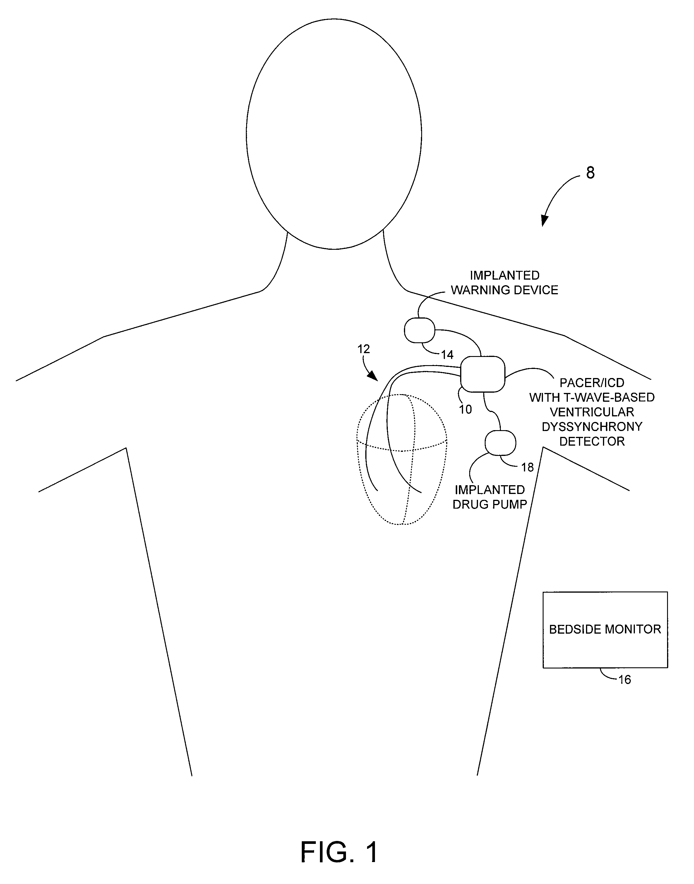
[0036]FIG. 1 illustrates an implantable medical system 8 capable of detecting parameters representative of ventricular dyssynchrony based on T-wave measurements and also for controlling delivery of appropriate therapy in response thereto. To this end, a pacer / ICD 10 (or other implantable medical device) receives IEGM signals or other electrical cardiac signals from a set of cardiac pacing / sensing leads 12. In FIG. 1, only two leads are shown. A more complete set of leads is illustrated in FIG...


PUM


Abstract

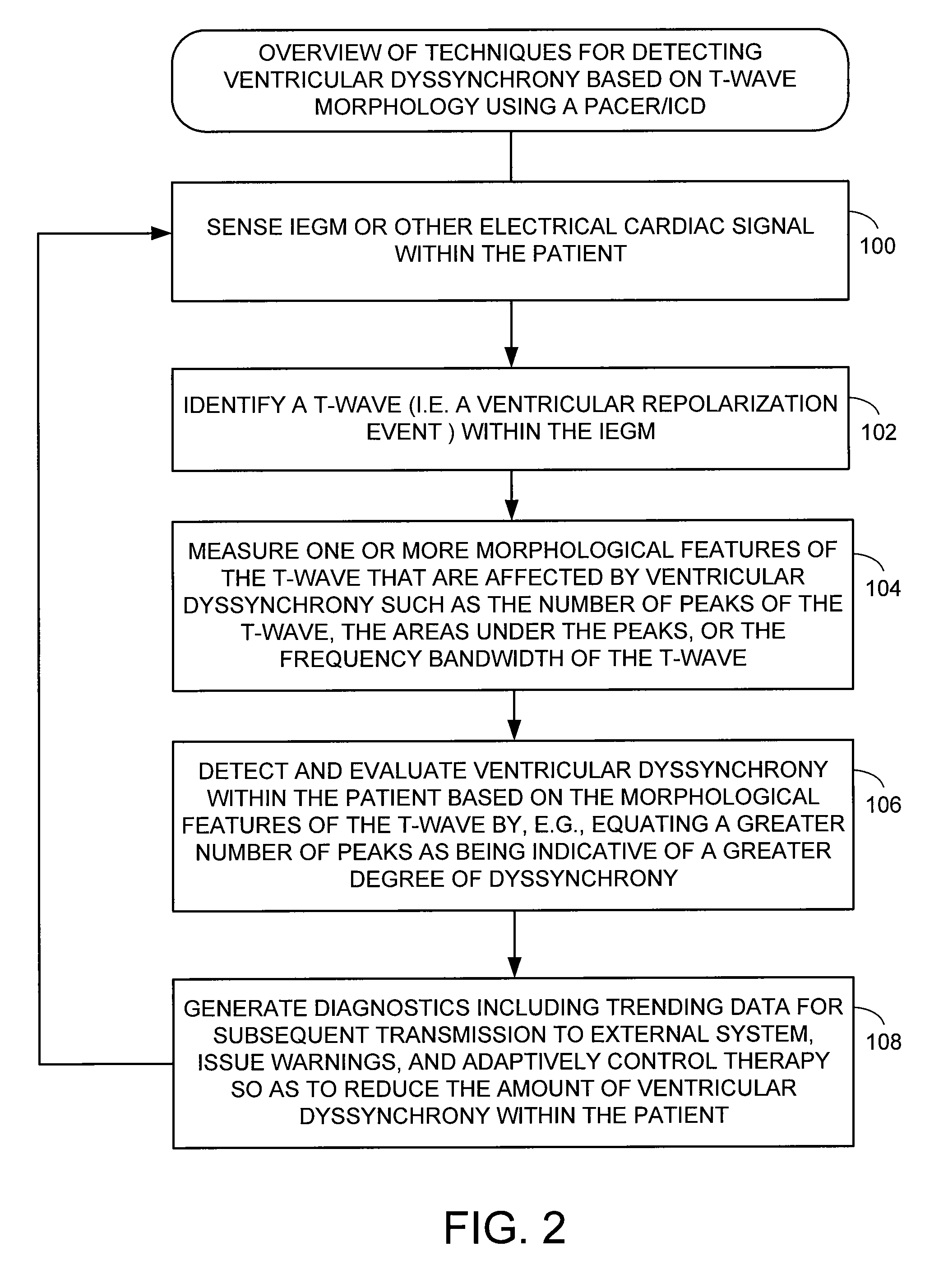
Techniques are provided for detecting and evaluating ventricular dyssynchrony based on morphological features of the T-wave and for controlling therapy in response thereto. For example, the number of peaks in the T-wave, the area under the peaks, the number of points of inflection, and the slope of the T-wave can be used to detect ventricular dyssynchrony and evaluate its severity. As ventricular dyssynchrony often arises due to heart failure, the degree of dyssynchrony may also be used as a proxy for tracking the progression of heart failure. Pacing therapy is automatically and adaptively adjusted based on the degree of ventricular dyssynchrony so as to reduce the dyssynchrony and thereby improve cardiac function.

Description

FIELD OF THE INVENTION[0001]The invention generally relates to implantable medical devices, such as pacemakers or implantable cardioverter / defibrillators (ICDs), and in particular to techniques for evaluating ventricular dyssynchrony within heart failure patients and for controlling therapy in response thereto.BACKGROUND OF THE INVENTION[0002]Heart failure is a debilitating disease in which abnormal function of the heart leads in the direction of inadequate blood flow to fulfill the needs of the tissues and organs of the body. Typically, the heart loses propulsive power because the cardiac muscle loses capacity to stretch and contract. Often, the ventricles do not adequately eject or fill with blood between heartbeats and the valves regulating blood flow become leaky, allowing regurgitation or back-flow of blood. The impairment of arterial circulation deprives vital organs of oxygen and nutrients. Fatigue, weakness and the inability to carry out daily tasks may result. Not all heart...

Claims


Application Information

Patent Timeline
IPC IPC(8): A61N1/00
CPCA61B5/0452A61N1/3627A61N1/365A61B5/7239A61B5/349A61B5/355
Inventor PILLAI, AJITNAWARE, MIHIRPANESCU, DORIN
Owner PACESETTER INC
Learn More