System and method for improving the efficiency and reliability of a broadband transistor switch for periodic switching applications

Inactive Publication Date: 2010-03-16
UNITED STATES OF AMERICA
View PDF9 Cites 8 Cited by
  • Summary
  • Abstract
  • Description
  • Claims
  • Application Information

AI Technical Summary

Benefits of technology

[0015]The concept is that an ideal switch can be used to efficiently convert a DC power source to a square-wave and that an ideal diode can be used to convert a square-wave source to DC. A nearly ideal switch can be emulated by the collector-emitter path of a transistor. Recognizing that the base-emitter junction is a diode, allows the basic concept to be employed to convert the transistor to be employed to convert the transistor into a nearly ideal switch.
[0016]This concept allows precision control of the base-emitter current in the “ON” state of the switch and allows precision control of the base-emitter reverse bias in the “OFF” state of the switch. If the “ON” state b

Problems solved by technology

Direct Current (DC) power for operation is difficult to supply because of the long length and/or the small size of the sensor tethers.
The driven dev

Method used


Image

  • System and method for improving the efficiency and reliability of a broadband transistor switch for periodic switching applications
  • System and method for improving the efficiency and reliability of a broadband transistor switch for periodic switching applications
  • System and method for improving the efficiency and reliability of a broadband transistor switch for periodic switching applications

Examples


Embodiment Construction

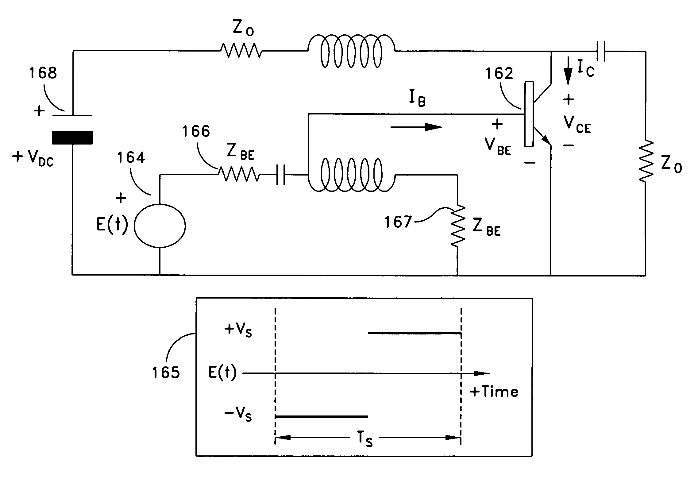
[0046]The description of a switch driver design is presented in five sections. In a first section, concepts are introduced that explain circuit operation in the following sections. In a second section, the operation of an energy efficient square-wave generator is disclosed. The square-wave generator circuit provides a foundation for the amplitude-phase modulator design disclosed in a fifth section. In a third section, an energy efficient [square-wave]-to-DC converter is disclosed, which provides a foundation for the switch driver design disclosed in a fourth section.

Introduction to the Disclosed Method

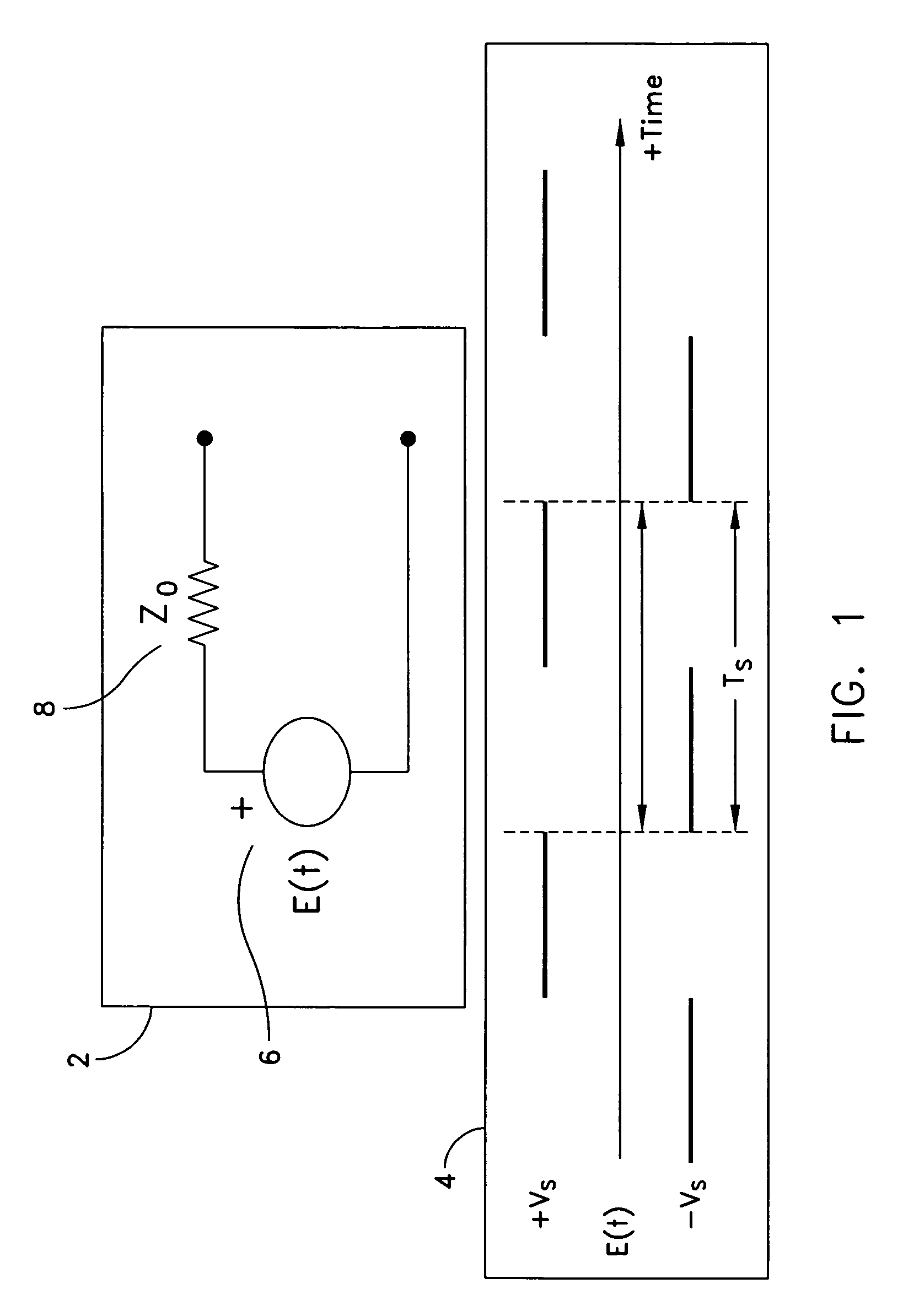
[0047]In FIG. 1, a Thevenin-Equivalent source 2 is shown. A voltage 4 of a signal generator 6 switches between a positive state, +VS and a negative state, −VS, in which the states have the same magnitude but opposite polarity. The switching operation is periodic with a period, TS, and with equal dwell times in each state. Thus, the average value of the generator voltage is zero. Furthe...


PUM


Abstract

A driver circuit is provided for enabling a transistor collector-emitter path to be used as a broadband periodic switch. The broadband driver circuit controls the magnitude of the transistor base-emitter current in order to enable a CLOSED switch state and to simultaneously control the magnitude of the transistor base-emitter reverse-bias voltage in order to enable the OPEN-switch state. The precise control of these parameters minimizes base-charge storage and prevents reverse-breakdown failure.

Description

STATEMENT OF GOVERNMENT INTEREST[0001]The invention described herein may be manufactured and used by or for the Government of the United States of America for governmental purposes without the payment of any royalties thereon or therefor.CROSS-REFERENCE TO RELATED APPLICATIONS[0002]The application submitted herein is related to: U.S. patent application Ser. No. 12 / 022,506, filed on Jan. 30, 2008 entitled “A Method for Coupling a Direct Current Power Source Across a Dielectric Membrane or Other Non-Conducting Membrane” and U.S. patent application Ser. No. 12 / 022,537 filed on Jan. 30, 2008 entitled “A Method for Coupling a Direct Current Power Source Across a Nearly Frictionless High-Speed Rotation Boundary”. Both applications are by the inventor, Dr. Donald H. Steinbrecher.BACKGROUND OF THE INVENTION[0003](1) Field of the Invention[0004]The present invention relates to a system and method of use for a broadband transistor switch in periodic switching applications.[0005](2) Descriptio...

Claims


Application Information

Patent Timeline
IPC IPC(8): H03B1/00H03K17/60
CPCH03K17/601
Inventor STEINBRECHER, DONALD H.
Owner UNITED STATES OF AMERICA
Why Eureka
Try Eureka