
High performance variable gain amplifier, method of use and design structure

a gain amplifier and variable gain technology, applied in the circuit field, can solve the problems of poor input impedance matching at differential agc (automatic gain control) levels, and achieve the effect of maximizing linearity

Inactive Publication Date: 2010-03-30
IBM CORP
View PDF4 Cites 0 Cited by
  • Summary
  • Abstract
  • Description
  • Claims
  • Application Information

AI Technical Summary

Benefits of technology

The invention is a circuit that includes multiple stages that have a common input and output, and individual control level inputs. The circuit also includes a fixed stage that is always "on" from the common input. The method involves setting cross points, choosing gains, and maximizing linearity by setting degeneration resistor values and DC bias currents for each stage, and cascading multi-stage cores. The design structure is a machine-readable medium that includes a plurality of differential stages with a common input, a common control level input, and individual control level inputs. The technical effects of the invention include improved linearity and efficiency in signal processing, as well as improved performance and reliability of electronic circuits.

Problems solved by technology

However, in known circuits, there is poor input impedance matching at differential AGC (automatic gain control) levels due to de-generation, as well as low dynamic range and no high IP3 at high gain.

Method used


Image

  • High performance variable gain amplifier, method of use and design structure
  • High performance variable gain amplifier, method of use and design structure
  • High performance variable gain amplifier, method of use and design structure

Examples


Embodiment Construction

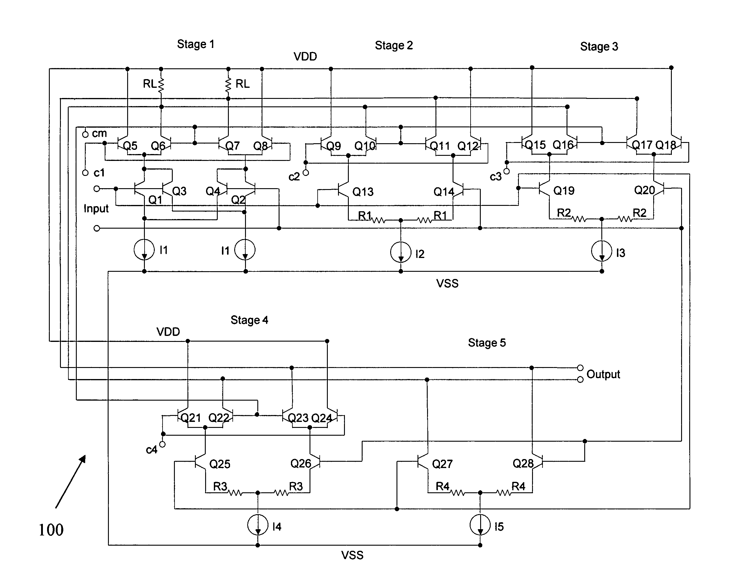
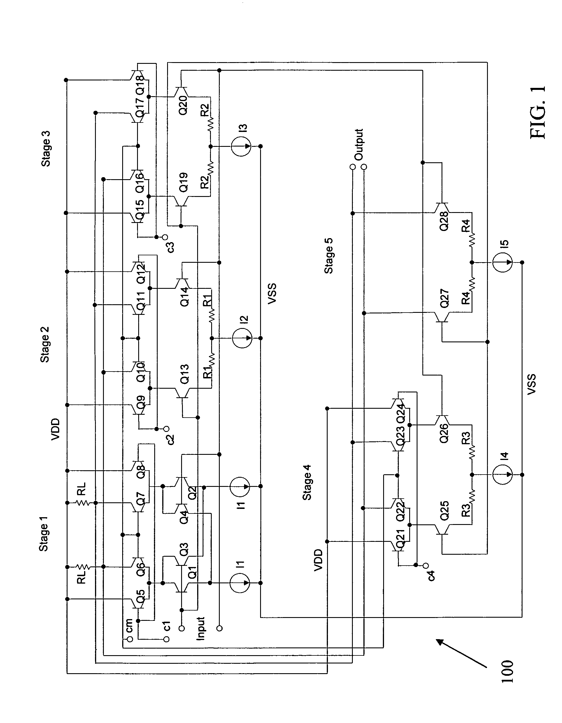
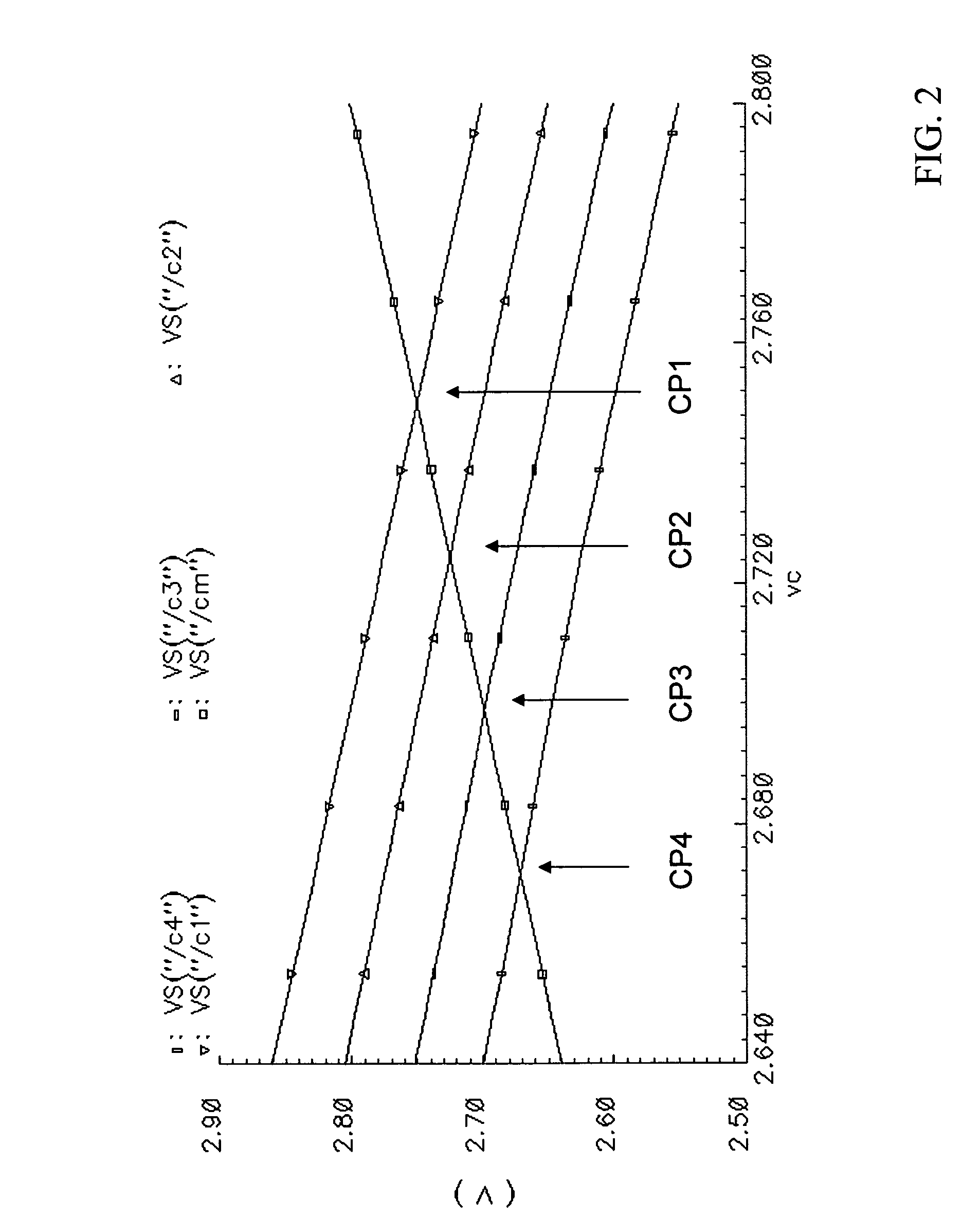
[0017]The invention relates to a circuit and method of use and, more particularly, to a high performance variable gain amplifier, method of use and design structure on which the circuit resides. In implementation, the high performance variable gain amplifier is a multi-stage variable gain amplifier (VGA) circuit, where each stage is connected to inputs, to outputs and to a pair of analog control voltages. The bias of each stage is optimized for linearity and transconductance at its cross point. The multi-stage architecture also provides a wide dynamic range with good linearity and the optimized transconductance of each stage minimizes the noise figure. Also, because the circuit has a constant bias, the input impedance is fixed and impedance matching is straightforward.

[0018]Advantageously, the circuit is a high linear and low noise figure circuit at a dynamic range much beyond 10 dB and more particularly at about 33 dB. In embodiments, the circuit exhibits approximately 5 dB NF (noi...


PUM


Abstract

A circuit of high performance variable gain amplifier, method of use and design structure on which the subject circuit resides is provided. The circuit comprises a plurality of differential stages having a common input, and output, a common control level input CM and respective individual control level inputs Cx. The circuit also includes a fixed stage that always is biased to an “on” state from the common input.

Description

GOVERNMENT LICENSING RIGHTS[0001]The U.S. Government has a paid-up license in this invention and the right in limited circumstances to require the patent owner to license others on reasonable terms as provided for by the terms of contract No. 002753 awarded by the Maryland Procurement Office under government program “JTRS Spiral2 CoreRadio1”.FIELD OF THE INVENTION[0002]The invention relates to a circuit and method of use and, more particularly, to a high performance variable gain amplifier, method of use and design structure on which the subject circuit resides.BACKGROUND DESCRIPTION[0003]A variable gain amplifier is an electronic amplifier that varies its gain depending on a control voltage (often abbreviated CV). The variable gain amplifier can be fabricated as a CMOS or BiCMOS circuit and has many applications, including handling dynamic signal level in transmitter and receiver of a radio device for radio-freq and microwave applications. For example, variable gain amplifiers have...

Claims


Application Information

Patent Timeline
Patent Type & Authority Patents(United States)
IPC IPC(8): H03F3/45
CPCH03F3/45089H03F2203/45052H03F2203/45302H03F2203/45318H03F2203/45366H03F2203/45392H03F2203/45702H03G1/0023
Inventor CHI, HOWARD H.
Owner IBM CORP
Learn More