Display driver and display driving method
a technology of display driver and driver, applied in the field of display driver, can solve the problems of increasing the circuit scale and affecting the effect of reducing the fluctuation of the holding potential
- Summary
- Abstract
- Description
- Claims
- Application Information
AI Technical Summary
Benefits of technology
Problems solved by technology
Method used
Image
Examples
first embodiment
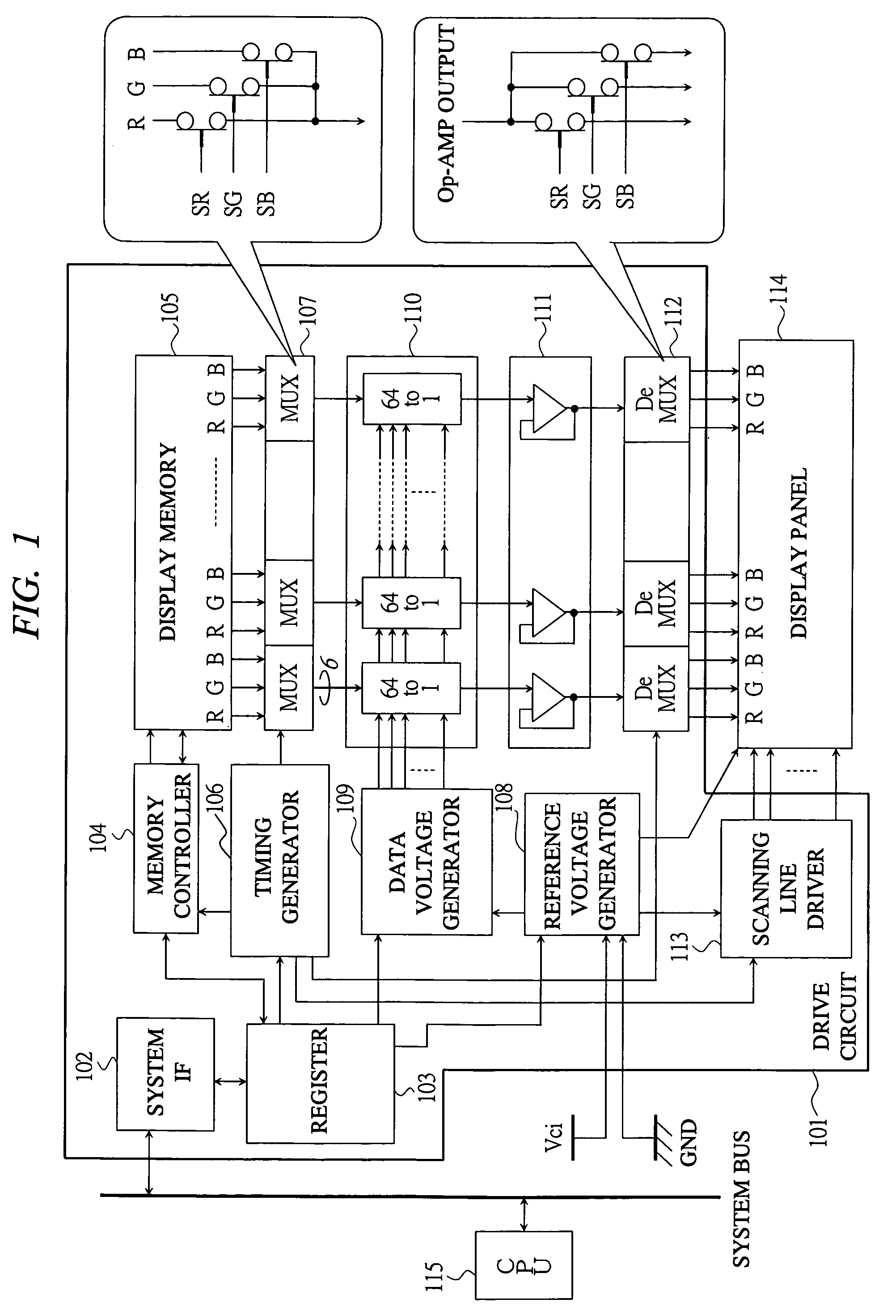
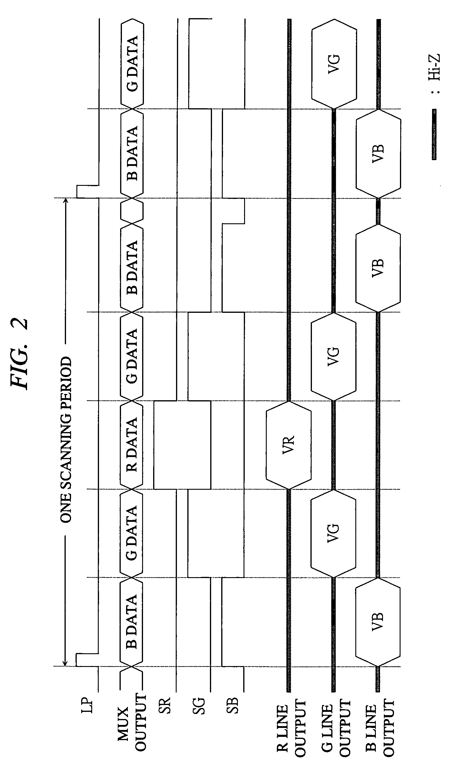
[0022]A configuration and an operation of a display driver according to a first embodiment of the present invention will be described below with reference to FIG. 1 and FIG. 2.
[0023]First, FIG. 1 shows a block configuration of a display driver according to a first embodiment of the present invention. In FIG. 1, a reference numeral 101 denotes a drive circuit, 102 denotes a system interface (IF), 103 denotes a register, 104 denotes a memory controller, 105 denotes a display memory, 106 denotes a timing generator, 107 denotes a multiplexer (MUX), 108 denotes a reference voltage generator, 109 denotes a data voltage generator, 110 denotes a data voltage selector (64 to 1), 111 denotes an operational amplifier (Op-AMP), 112 denotes a demultiplexer (DeMUX), 113 denotes a scanning line driver, 114 denotes a display panel, and 115 denotes a CPU.
[0024]The drive circuit 101 is a so-called display memory built-in type controller driver, and it includes achieving means according to the present...
second embodiment
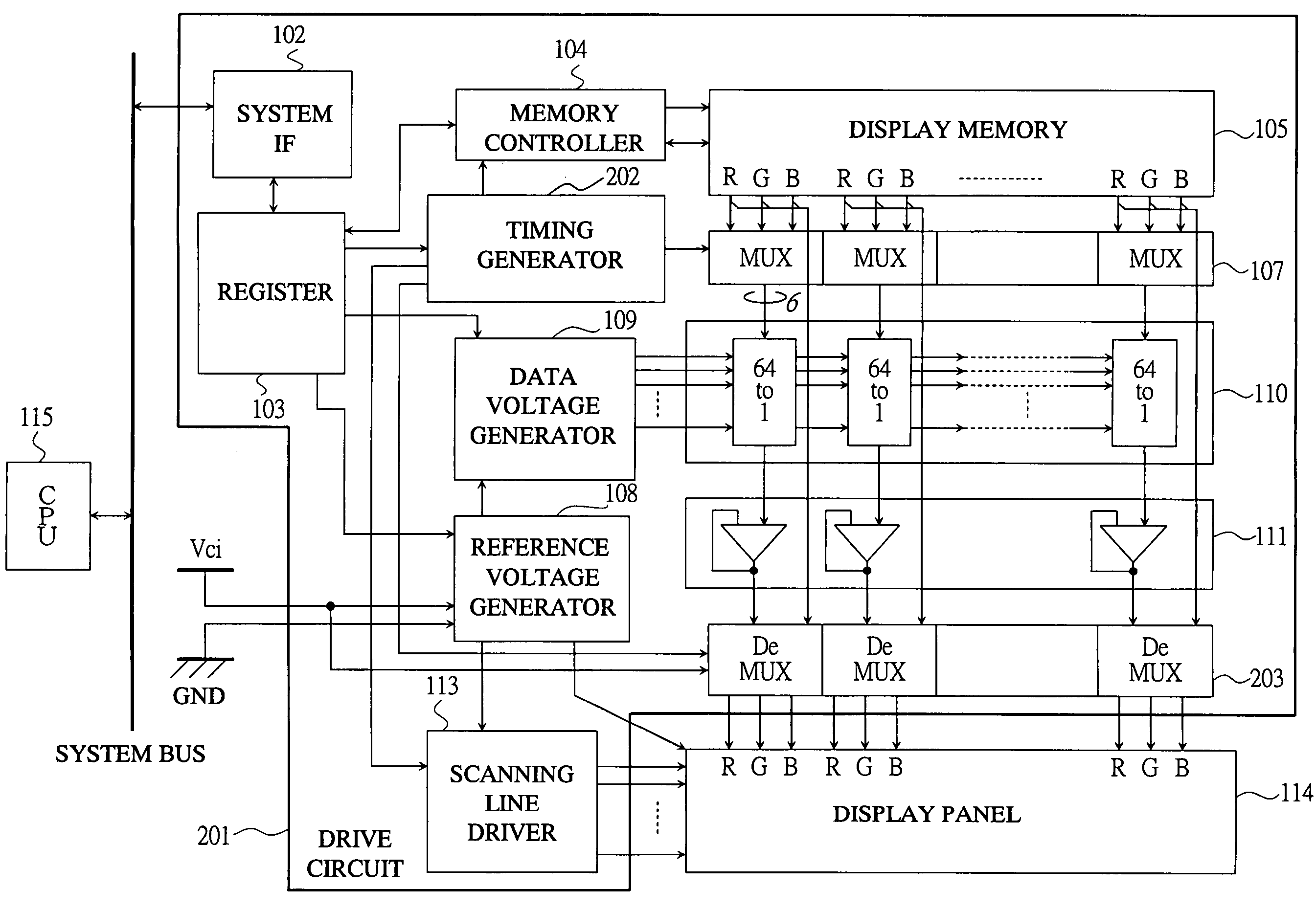
[0044]Next, a configuration and an operation of a display driver according to a second embodiment of the present invention will be described with reference to FIG. 3 to FIG. 5.
[0045]As described above, in the first embodiment of the present invention, the method in which the data voltage is applied in the order of B→G→R→G→B has been described. In this embodiment, the B line is driven just after starting the one scanning period, and since the outputs to the G line and the R line become high impedance in this period, the potential applied in the previous scanning period is held. In this case, assuming a so-called Vcom alternating current drive in which the voltage Vcom is alternated in each one scanning period, since the Vcom electrode and the data line are capacity-coupled to each other, the holding voltage of the data line transits in conjunction with the transition of the voltage Vcom, and the holding potential after the transition exceeds the amplitude range of the data voltage in...
third embodiment
[0053]Next, a configuration and an operation of a display driver according to a third embodiment of the present invention will be described with reference to FIG. 6 to FIG. 8.
[0054]In the third embodiment of the present invention, two types of pre-charge levels are provided for the pre-charge level of the fixed potential described in the second embodiment of the present invention so as to further reduce the potential difference between before and after the first data voltage is applied, thereby achieving the further improvement of the operation margin in the time-sharing drive. In this embodiment, two types of pre-charge levels are the power supply voltages Vci and GND, and the pre-charge is controlled by using the display data.
[0055]FIG. 6 shows a block configuration of a display driver according to the third embodiment of the present invention. In FIG. 6, a reference numeral 301 denotes a drive circuit, and 302 denotes a demultiplexer. Since the other blocks are the same as the co...
PUM
 Abstract
Description
Claims
Application Information
 - R&D
- Intellectual Property
- Life Sciences
- Materials
- Tech Scout
- Unparalleled Data Quality
- Higher Quality Content
- 60% Fewer Hallucinations
Browse by: Latest US Patents, China's latest patents, Technical Efficacy Thesaurus, Application Domain, Technology Topic, Popular Technical Reports.
© 2025 PatSnap. All rights reserved.Legal|Privacy policy|Modern Slavery Act Transparency Statement|Sitemap|About US| Contact US: help@patsnap.com


