Method and device for regenerating a particle filter integrated into an exhaust line of an internal combustion engine

a technology of internal combustion engine and particle filter, which is applied in the direction of auxillary pretreatment, electrical control, separation process, etc., can solve the problems of engine malfunction, back pressure buildup, and inability to control the combustion inside the filter, so as to achieve simple and effective exotherm management

Inactive Publication Date: 2010-04-13
INST FR DU PETROLE +1
View PDF10 Cites 11 Cited by
  • Summary
  • Abstract
  • Description
  • Claims
  • Application Information

AI Technical Summary

Benefits of technology

[0010]The goal of the present invention is to overcome the drawbacks referred to above by simple, effective management of the exotherm of the particle filter, even when this filter is catalyzed.

Problems solved by technology

However, these particles and soots have the property of clogging the filter after a certain usage period and causing back-pressure to build up in the exhaust line, which may cause an engine malfunction.
However, the combustion inside the filter cannot be controlled, which can lead to very high temperatures inside it.
These temperatures can cause the material of which the filter is made to deteriorate or even be destroyed.
The problem is even more significant when other functions are built into this filter.
This has the drawback of causing deterioration of the catalytic phases present on this filter, which can no longer fulfill their function of converting the polluting gaseous phases present in the exhaust gases.
Such an arrangement, although it is satisfactory, has the non-negligible drawback of not giving a true representation of the various temperatures prevailing in various regions of the filter, mainly when the temperature sensor is disposed downstream of the filter.
When there is a local temperature elevation inside the filter, the sensor downstream of the filter cannot pick up such an increase and the regeneration continues, with the risk of locally degrading the filter.

Method used


Image

  • Method and device for regenerating a particle filter integrated into an exhaust line of an internal combustion engine
  • Method and device for regenerating a particle filter integrated into an exhaust line of an internal combustion engine
  • Method and device for regenerating a particle filter integrated into an exhaust line of an internal combustion engine

Examples


Embodiment Construction

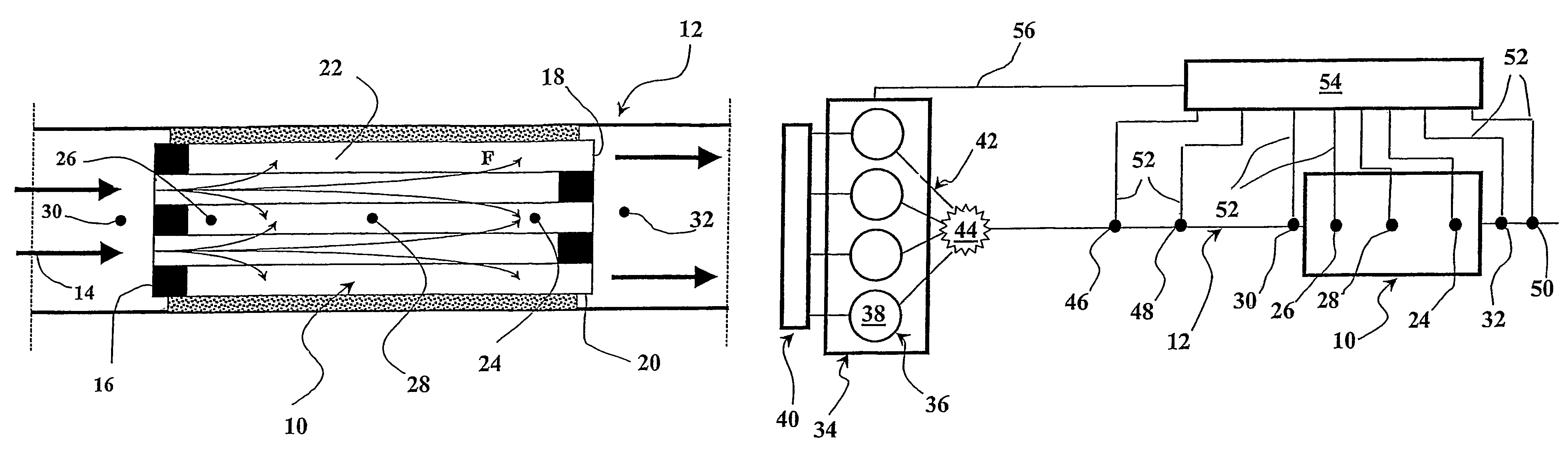
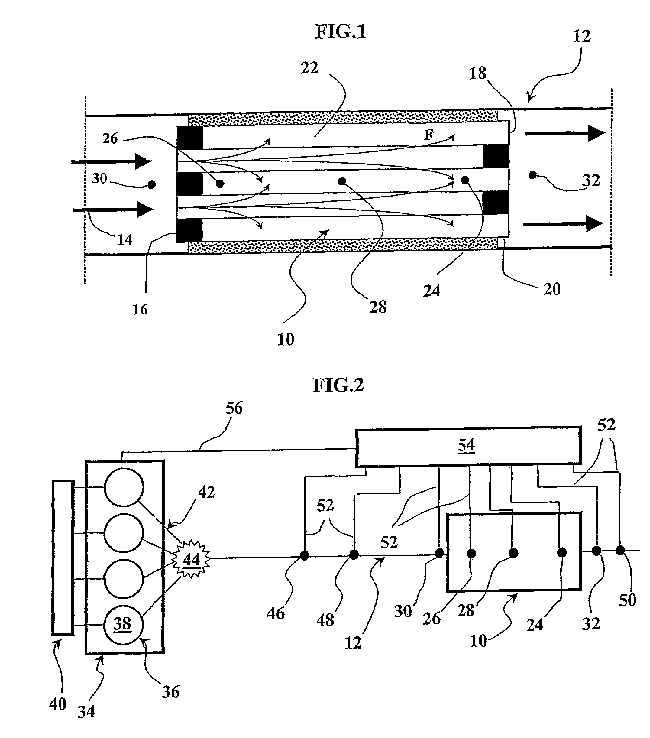
[0029]In FIG. 1, the particle filter 10 is accommodated in an exhaust line 12. This filter is traversed by the exhaust gases 14 which circulate, as indicated by the arrows, from the inflow face 16 of the filter to its outflow face 18. As is known of itself, the filter is made of a monolith 20 having channels 22 disposed in the circulation direction of gases 14. As an example, as can be seen in FIG. 1, some of the channels are obstructed at the inflow face 16 while others are obstructed at the outflow face 18 in order to achieve circulation of the exhaust gases in this filter, as illustrated by arrows F.

[0030]Of course, without thereby departing from the invention, the channels 22 of this monolith can be coated with catalytic phases for converting the polluting gas phases of the exhaust gases, such as CO, HC, or NOx.

[0031]In view of the large volume of the particle filter, which can be greater than three liters, and the heterogeneity of the particle and soot deposits along channels 2...


PUM

PropertyMeasurementUnit
volumeaaaaaaaaaa
distanceaaaaaaaaaa
temperatureaaaaaaaaaa

Abstract

The invention relates to a method for regenerating a particle filter (10) integrated into an exhaust line (12) of an internal combustion engine (34), wherein the exhaust gas flows into the filter via an inflow surface (16) and exit the filter via an outflow surface (18). According to the invention, the internal temperature of at least two regions of the filter (10) is monitored during regeneration of the filter; the oxygen content of the exhaust gas is reduced if at least one of the monitored temperatures rises above a critical temperature; the oxygen content of the exhaust gas is increased in order to continue regeneration if all of the monitored temperatures are below said critical temperature.

Description

BACKGROUND OF THE INVENTION[0001]The present invention relates to a method and a device for regenerating a particle filter built into an exhaust line of an internal combustion engine, particularly of the diesel type.[0002]It relates in particular to a method and a device for regulating the heat release, or exotherm, of the particle filter.[0003]In general, a particle filter is used to pick up particles and soot contained in the exhaust gases and prevent them from being released into the atmosphere. However, these particles and soots have the property of clogging the filter after a certain usage period and causing back-pressure to build up in the exhaust line, which may cause an engine malfunction.[0004]It is known that as soon as this filter reaches a predetermined clogging level, a filter regeneration sequence is triggered, generally by the engine control. This regeneration sequence consists essentially of burning the particles and soots present in this filter. For this purpose, th...

Claims


Application Information

Patent Timeline
Patent Type & Authority Patents(United States)
IPC IPC(8): F01N3/00F01N3/023F01N3/035F01N3/08F01N9/00F01N13/02F02D41/02
CPCF01N3/023F01N9/002F02D41/025F01N13/009F02D41/029F01N2560/06F01N2560/14F02D2200/0802Y02T10/26Y02T10/47F02D41/028Y02T10/12Y02T10/40
Inventor NOIROT, REMICASTAGNE, MICHELDEMENTHON, JEAN-BAPTISTE
Owner INST FR DU PETROLE
Why Eureka
Try Eureka