Heart wall tension reduction apparatus and method

a technology for reducing the tension of the heart wall and the heart, which is applied in the field of apparatus for treating the failing heart, can solve the problems of increasing the requirement of systolic contraction, increasing the wall tension, and the heart continues to dilate, so as to reduce the energy consumption of the failing heart, and reduce the effect of isovolumetric contraction

Inactive Publication Date: 2010-04-13
EDWARDS LIFESCIENCES LLC
View PDF542 Cites 39 Cited by
  • Summary
  • Abstract
  • Description
  • Claims
  • Application Information

AI Technical Summary

Benefits of technology

[0010]The present invention pertains to a non-pharmacological, passive apparatus and method for the treatment of a failing heart. The device is configured to reduce the tension in the heart wall. It is believed to reverse, stop or slow the disease process of a failing heart as it reduces the energy consumption of the failing heart, decreases isovolumetric contraction, increases sarcomere shortening during contraction and increases isotonic shortening which in turn increases stroke volume. The device reduces wall tension during diastole and systole.

Problems solved by technology

With damage to the myocardium or chronic volume overload, however, there are increased requirements put on the contracting myocardium to such a level that this compensated state is never achieved and the heart continues to dilate.
The basic problem with a large dilated left ventricle is that there is a significant increase in wall tension and / or stress both during diastolic filling and during systolic contraction.
However, in a failing heart, the ongoing dilatation is greater than the hypertrophy and the result is a rising wall tension requirement for systolic contraction.
This is felt to be an ongoing insult to the muscle myocyte resulting in further muscle damage.
Additionally, because of the lack of cardiac output, there is generally a rise in ventricular filling pressure from several physiologic mechanisms.
These drug therapies offer some beneficial effects but do not stop the progression of the disease.
Heart transplantation has serious limitations including restricted availability of organs and adverse effects of immunosuppressive therapies required following heart transplantation.
However, this extremely invasive procedure reduces muscle mass of the heart.

Method used


Image

  • Heart wall tension reduction apparatus and method
  • Heart wall tension reduction apparatus and method
  • Heart wall tension reduction apparatus and method

Examples


embodiment 116

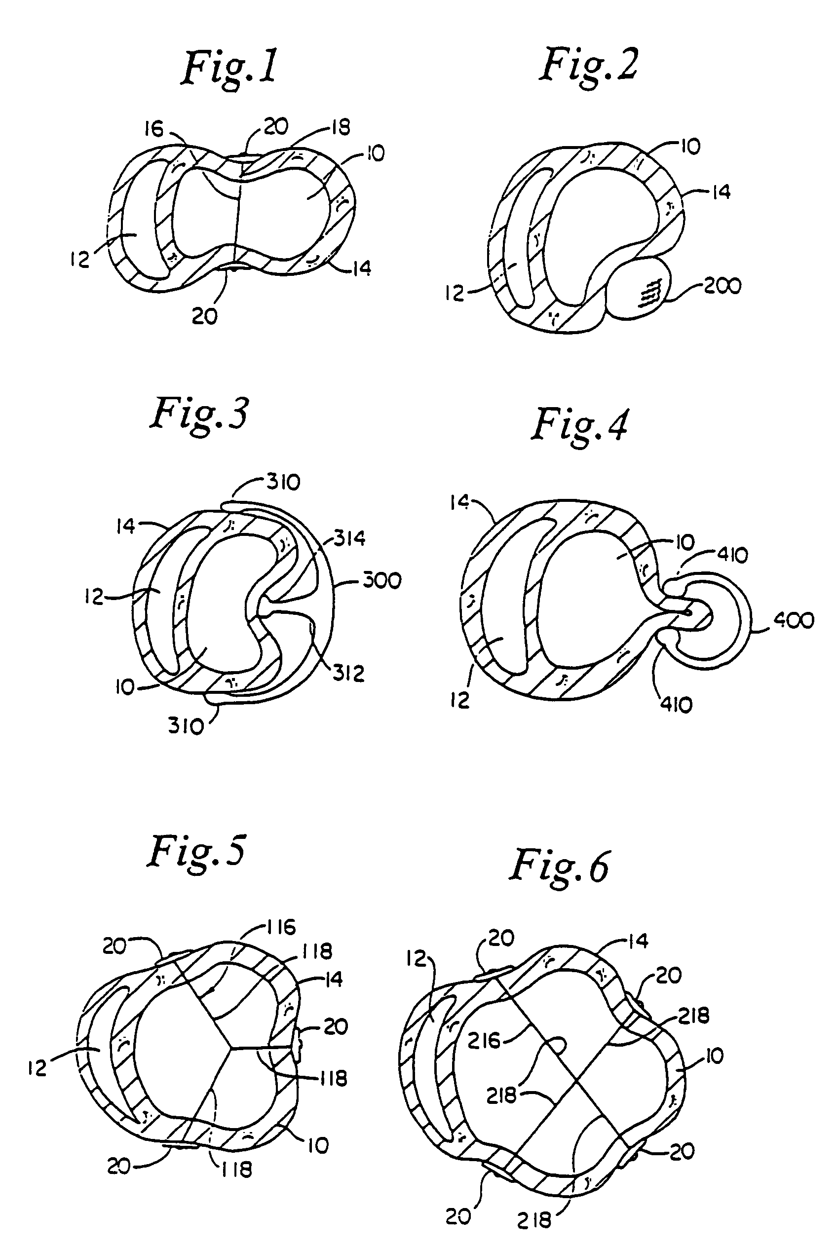
[0066]FIG. 5 shows an alternate embodiment of the splint of FIG. 1 referred to in FIG. 5 by the numeral 116. The embodiment 116 shown in FIG. 5 includes three tension members 118 as opposed to a single tension member 18 as shown in FIG. 1. FIG. 6 shows yet another embodiment of the splint 216 having four tension members 218. It is anticipated that in some patients, the disease process of the failing heart may be so advanced that three, four or more tension members may be desirable to reduce the heart wall stresses more substantially than possible with a single tension member as shown in FIG. 1.

embodiment 316

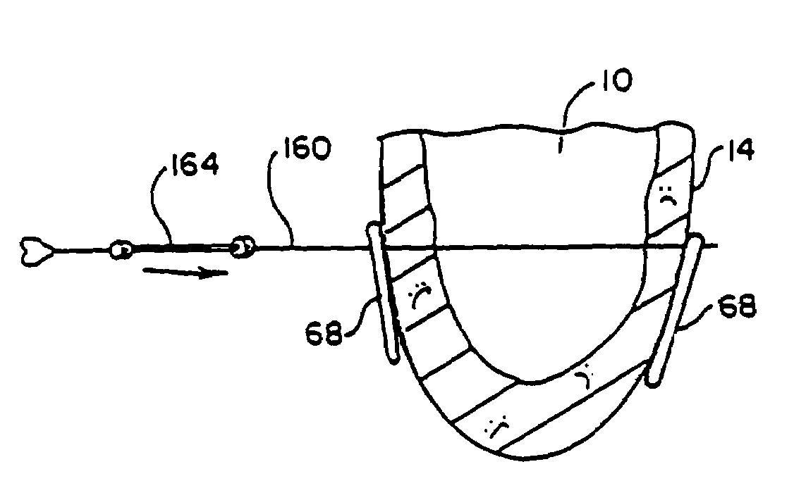
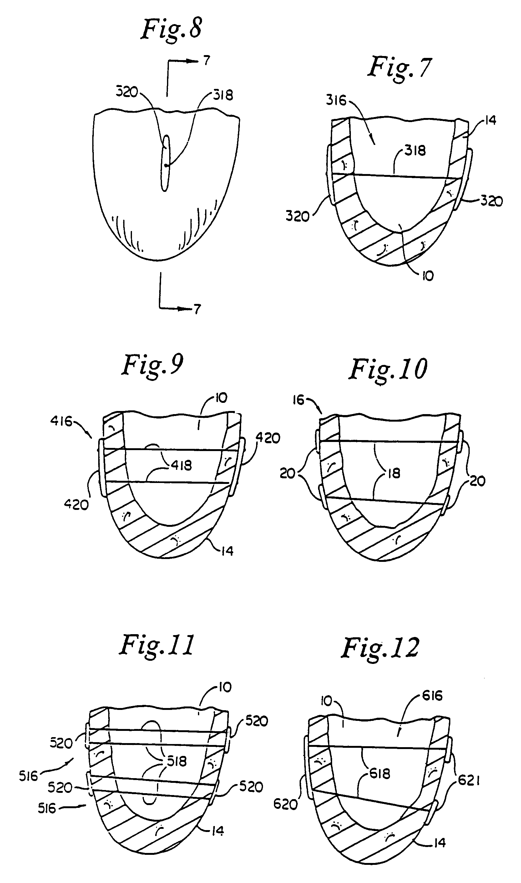
[0067]FIG. 7 is a partial vertical cross-section of human heart 14 showing left ventricle 10. In FIG. 7, another splint embodiment 316 is shown having a tension member 318 extending through left ventricle 10. On opposite ends of tension member 318 are disposed elongate anchors or pads 320. FIG. 8 is an end view of tension member 318 showing elongate anchor 320.

[0068]FIG. 9 shows another embodiment of a splint 416 disposed in a partial vertical cross-section of human heart 14. Splint 416 includes two elongate anchors or pads 420 similar to those shown in FIGS. 7 and 8. In FIG. 9, however, two tension members 418 extend through left ventricle 10 to interconnect anchors 420 on opposite sides of heart 14.

[0069]FIG. 10 is a vertical cross section of heart 14 showing left ventricle 10. In this case, two splints 16 are disposed through left ventricle 10 and vertically spaced from each other to resemble the configuration of FIG. 9.

[0070]FIG. 11 is a vertical cross sectional view of the left...

embodiment 156

[0074]FIG. 14 shows an alternate embodiment 156 of the splint shown in FIG. 13. In this case lever members 154 are longer than members 54 as compression member 152 of splint 150 has been disposed to the exterior of left ventricle 10.

[0075]FIG. 15 is a vertical cross sectional view of left ventricle 10 of heart 14. An alternate embodiment 250 of the splint is shown on heart 14. A preferably relatively rigid frame member 256 extends through ventricle 10. Disposed on opposite ends of frame 250 are cantilever member 254. Disposed on cantilever members 254 are atraumatic pads 258. Cantilever members 254 can be positioned along frame member 256 such that atraumatic pads 258 press against heart 14 to compress chamber 10. FIG. 16 is an end view of frame member 256 showing cantilever members 254 and pads 258.

[0076]It should be understood that each of the embodiments described above should be formed from suitable biocompatible materials known to those skilled in the art. The tension members c...


PUM


Abstract

An apparatus for treatment of a failing heart by reducing the wall tension therein. In one embodiment, the apparatus includes a tension member for drawing at least two walls of a heart chamber toward each other. Methods for placing the apparatus on the heart are also provided.

Description

CROSS REFERENCE TO RELATED APPLICATION[0001]This application is a continuation of U.S. application Ser. No. 10 / 326,585, filed Dec. 20, 2002, now U.S. Pat. No. 6,755,777, which is a continuation of U.S. application Ser. No. 09 / 985,362, filed Nov. 2, 2001, now U.S. Pat. No. 6,514,194, which is a continuation of U.S. application Ser. No. 09 / 697,596, filed Oct. 27, 2000, now U.S. Pat. No. 6,332,863, which is a continuation of U.S. application Ser. No. 09 / 543,155, filed Apr. 4, 2000, now U.S. Pat. No. 6,165,120, which is a continuation of U.S. application Ser. No. 09 / 224,349, filed Jan. 4, 1999, now U.S. Pat. No. 6,165,119, which is a divisional of U.S. application Ser. No. 08 / 933,456, filed Sep. 18, 1997, now U.S. Pat. No. 5,961,440, which is a continuation-in-part of U.S. application Ser. No. 08 / 778,277, filed Jan. 2, 1997, now U.S. Pat. No. 6,050,936, the entire disclosures of each of which are herein incorporated by reference.FIELD OF THE INVENTION[0002]The present invention pertains...

Claims


Application Information

Patent Timeline
Patent Type & Authority Patents(United States)
IPC IPC(8): A61F2/00A61B17/00A61B17/04A61B17/12A61B17/122A61B19/00A61F2/02A61M31/00A61N1/362
CPCA61B17/00234A61F2/2487A61B17/1227A61B2017/00243A61B2017/0404A61B2017/0417A61B2017/0429Y10S623/91A61B2017/0461A61B2017/048A61B2017/0496A61F2/2481A61B2017/0435
Inventor SCHWEICH, CYRILMORTIER, TODD
Owner EDWARDS LIFESCIENCES LLC
Why Eureka
Try Eureka