Device for controlling and/or regulating a hydraulically activatable shifting element of a gearing mechanism and a gearing mechanism

a technology of hydraulic activation and gearing mechanism, which is applied in the direction of dynamo-electric gear control, gearing, transportation and packaging, etc., can solve the problems of increasing fuel consumption in vehicles equipped with automatic gearing mechanism, reducing the efficiency of automatic gearing mechanism, and high power consumption, so as to reduce cost and construction space, the effect of reducing the degree of efficiency

Inactive Publication Date: 2010-04-27
ZF FRIEDRICHSHAFEN AG
View PDF17 Cites 6 Cited by
  • Summary
  • Abstract
  • Description
  • Claims
  • Application Information

AI Technical Summary

Benefits of technology

[0013]In the case of the gearing mechanism according to the invention, which has shifting elements accommodated in an installation space connected with the oil sump of a gearing mechanism, each shifting element is assigned exactly one device in order to operate the shifting element, and each shifting element is assigned an independent means of actuation for hydraulic operation. In this way, a gearing mechanism configured, according to the invention, can be operated with lower power consumption and thus a higher degree of efficiency than gearing mechanisms that are known from the state of the art.
[0014]With an advantageous embodiment of the gearing mechanism, it is provided that the electric motors of the devices assigned to the shifting elements are driven by a common control and / or regulator unit in order to activate the shifting elements. Therewith exists the possibility of configuring the actuating devices provided to operate the shifting elements in a simple way that reduces cost and construction space.
[0015]Alternatively, a further development of the gearing mechanism, according to the invention, provides for the electric motors of the devices assigned to the shifting elements to be combined into groups and for each group of electric motors to be driven by a control and / or regulator unit assigned to that group in order to activate the shifting elements. This has the advantage of ensuring that if one of the control and / or regulator units fails, the electric motors that are combined into groups and driven by other control and / or regulator units of the gearing mechanism can still be operated and the gearing mechanism is still available for use, at least at in emergency operation.

Problems solved by technology

However, this has the disadvantage that the hydraulic-fluid volume flow delivered by the pumping device does not depend on requirements, but rather on rotation speed, i.e., is dependent on the number of revolutions produced by the main engine of the vehicle, the characteristic curve of the pumping device being designed for an operating state in which the pumping device displays its minimum delivery volume, and in which the users of the gearing mechanism, which have to be supplied with control pressure and hydraulic fluid via the hydraulic system, demonstrate a high requirement for hydraulic fluid.
In these operating ranges, the pumping device has an unnecessarily high power consumption, which reduces the efficiency of an automatic gearing mechanism and leads to an increase in fuel consumption in vehicles equipped with this type of automatic gearing mechanism compared to vehicles equipped with manual transmissions, whose shifting elements are essentially mechanically actuated.
A disadvantage of this method is that the portion of the hydraulic fluid of an automatic transmission that is normally supposed to be raised to a lower level of control pressure, such as a lubricant-circuit or cooling-oil circuit level, is condensed to the high holding-pressure level of the portion of the hydraulic fluid of an automatic transmission that is intended for the actuation of multiple-disk clutch or multiple-disk brakes.
This also means that the power consumption of the pumping device in these hydraulic systems is higher than that needed to supply the users of an automatic transmission.
This leads to impairment of the efficiency of an automatic transmission and to an undesirably high fuel consumption by the vehicle.

Method used


Image

  • Device for controlling and/or regulating a hydraulically activatable shifting element of a gearing mechanism and a gearing mechanism
  • Device for controlling and/or regulating a hydraulically activatable shifting element of a gearing mechanism and a gearing mechanism
  • Device for controlling and/or regulating a hydraulically activatable shifting element of a gearing mechanism and a gearing mechanism

Examples


Embodiment Construction

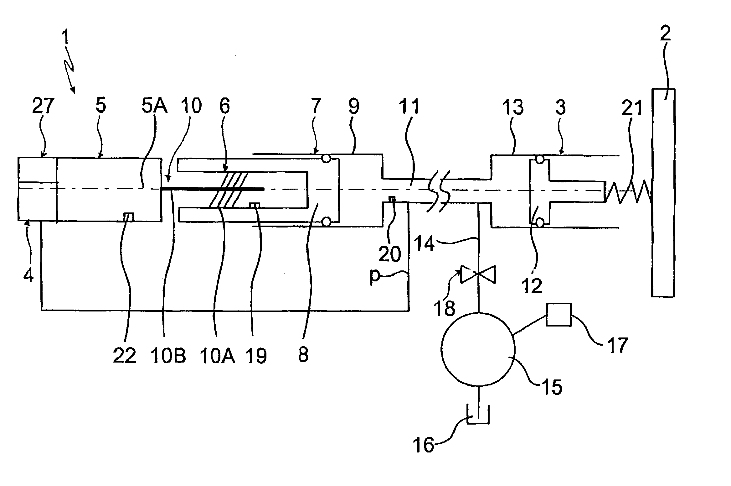
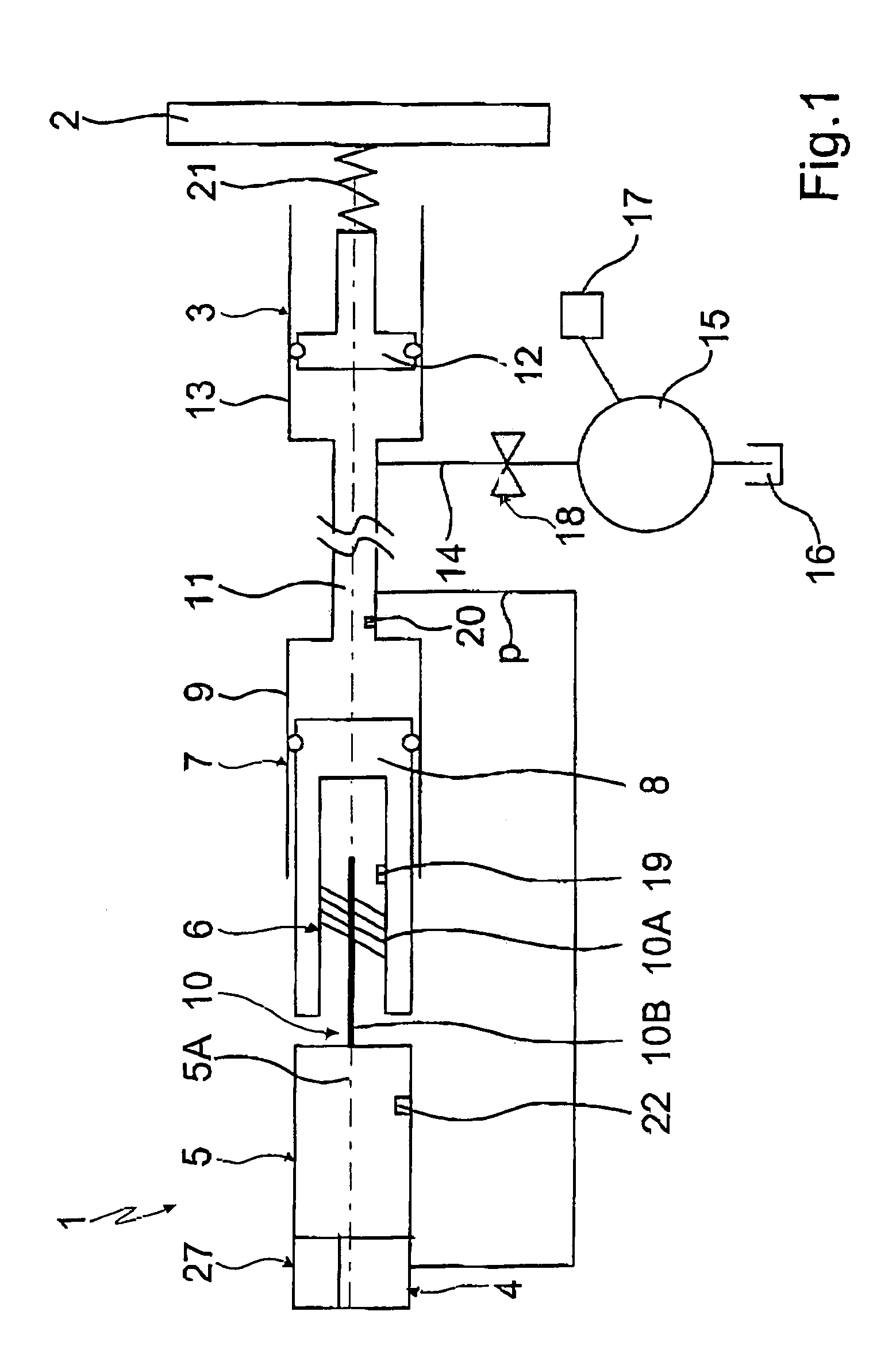
[0020]FIG. 1 presents a schematic diagram of a device 1 for controlling and / or regulating a hydraulically operated shifting element 2 of a gearing mechanism (not shown in detail), the element being accommodated in an installation space of the gearing mechanism that is connected with the oil sump of the gearing mechanism. Here the shifting element 2 is placed in relation to the housing of the gearing mechanism in such a way that the shifting element 2 can come into contact with the hydraulic fluid in the oil sump. The shifting element 2 is configured with a piston-cylinder unit 3 that can be acted upon by a hydraulic operating pressure p, and in this example consists of a frictionally-engaged multiple disk clutch of an automatic gearing mechanism for engaging ordisengaging a gear ratio of an automatic gearing mechanism.

[0021]Furthermore, the device 1 shows a control and / or regulator unit 4 and an electric motor 5 that is actuated by it. In addition, there is provision for a drive tra...


PUM


Abstract

A device (1) is described for controlling and / or regulating a hydraulically activatable shifting element. The shifting element (2) is configured with a piston-cylinder unit (3) that can be acted upon by a hydraulic operating pressure (p) and can be arranged in an installation space that is connected to an oil sump of the gearing mechanism device. In addition, the device (1) is provided with an electric motor (5) that can be actuated by a control and / or regulator unit (4), and which is provided with a drive-transformer device (6) that has a functional connection to the electric motor (5), by way of which the rotational drive of the electric motor (5) can be transformed into the hydraulic operating pressure (p) for the shifting element (2).

Description

[0001]This application claims priority from German Application Serial No. 10 2005 058 776.3 filed Dec. 9, 2005.FIELD OF THE INVENTION[0002]The invention applies to a device for controlling and / or regulating at least one hydraulically activatable shifting element of a gearing mechanism, which is configured with a piston-cylinder unit that is acted upon by a hydraulic actuation pressure and a gearing mechanism.BACKGROUND OF THE INVENTION[0003]In the gearing mechanisms known from conventional practice, shifting elements are preferably hydraulically activated due to the demand for high power density. A central hydraulic control device normally produces a control pressure in a hydraulic system by way of pressure controllers and valve units placed downstream from them, along with the hydraulic fluid flows necessary to actuate the shifting elements. In the operation of an automatic gearing mechanism, the central hydraulic control device is supplied by a permanently driven oil pump, or as t...

Claims


Application Information

Patent Timeline
Patent Type & Authority Patents(United States)
IPC IPC(8): B60K3/00
CPCF16D29/005F16H61/0021F16H61/0202Y10T74/20024Y10T477/33Y10T74/18576
Inventor REISCH, MATTHIASGRUMBACH, MARTINDOMIAN, HANS-JORG
Owner ZF FRIEDRICHSHAFEN AG
Why Eureka
Try Eureka