
Vapor-compression evaporation system and method

a technology of evaporation system and evaporation chamber, which is applied in the direction of machine/engine, separation process, lighting and heating apparatus, etc., can solve the problems of high efficiency and achieve the effects of low cost, low cost and convenient evaporation

Inactive Publication Date: 2010-05-04
TEXAS A&M UNIVERSITY +1
View PDF35 Cites 35 Cited by
  • Summary
  • Abstract
  • Description
  • Claims
  • Application Information

AI Technical Summary

Benefits of technology

The invention is a system for compressing and cooling a vapor using a jet ejector. The system includes multiple vessels, a compressor, a pump, and heat exchangers. The heat exchangers are designed to blend gas streams with similar velocities, resulting in high efficiency. The system can be used in various applications such as compressors, heat pumps, and vacuum pumps. Another embodiment of the invention includes a high-efficiency liquid jet ejector for cost-effective dewatering. The system also includes a heat exchanger with a lower pressure drop and a plurality of plates inside a tube for improved heat transfer.

Problems solved by technology

This leads to high efficiencies, even using traditional jet ejectors.

Method used


Image

  • Vapor-compression evaporation system and method
  • Vapor-compression evaporation system and method
  • Vapor-compression evaporation system and method

Examples


Embodiment Construction

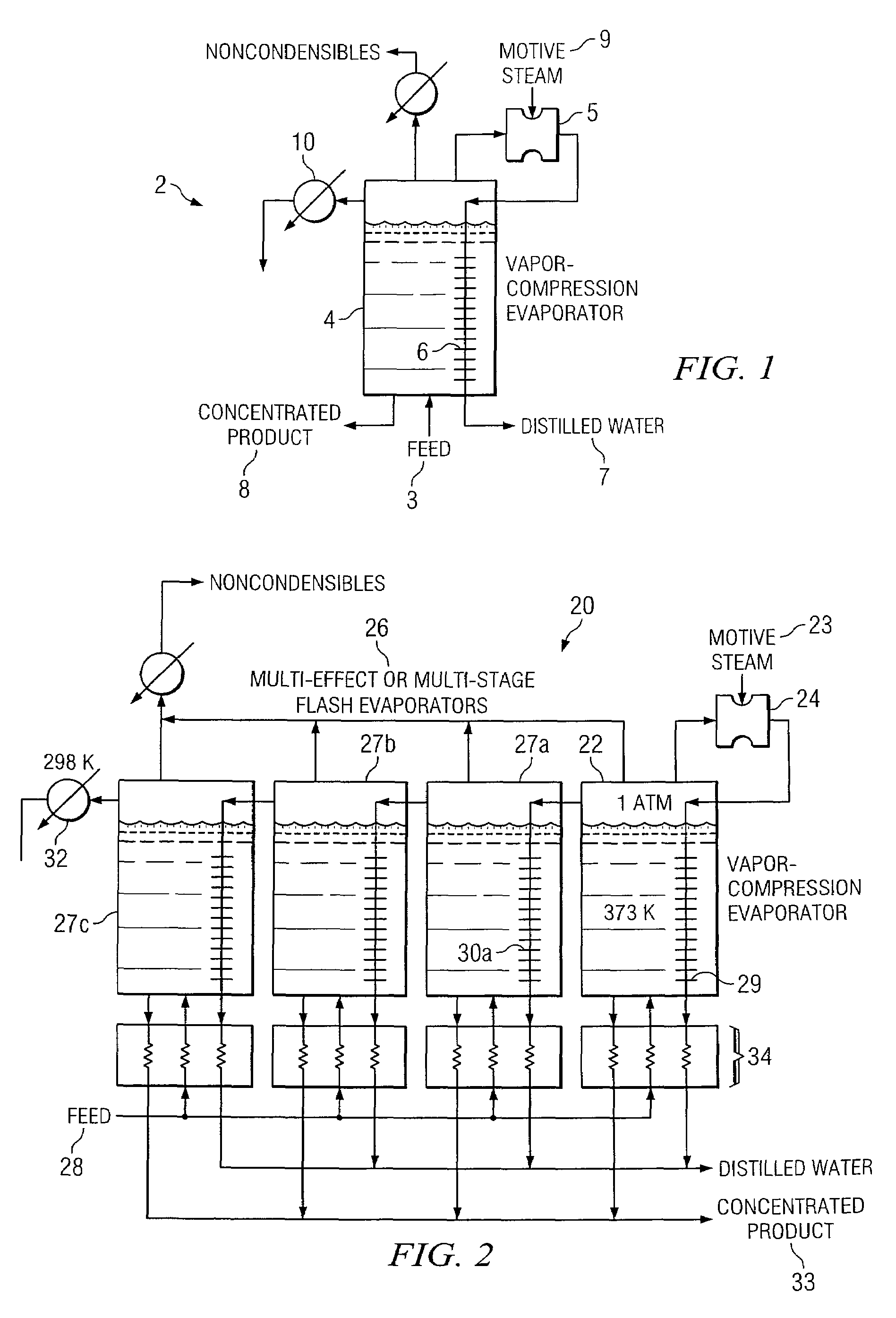
[0043]FIG. 1 illustrates a low-pressure vapor-compression evaporator system 2 performing desalination of salt water. A salt-containing feed 3 flows into an evaporator tank 4, which in this embodiment is operated under vacuum. Although, in the illustrated embodiment, feed 3 is a salt-containing feed, a sugar-containing feed or suitable feed is also contemplated by the present invention. The salt-containing feed 3 boils, producing low-pressure vapors. These vapors are removed from evaporator tank 4 using a jet ejector 5. The pressurized vapors exiting jet ejector 5 flow into a heat exchanger 6, where they condense. Because of the interaction of heat exchanger 6 and evaporator tank 4, the heat of condensation provides the heat of evaporation needed by the salt-containing feed 3. Distilled liquid water 7 is recovered from heat exchanger 6 in any suitable manner, and concentrated salt solution 8 is removed from evaporator tank 4 using any suitable devices. The motive steam 9 added to jet...


PUM


Abstract

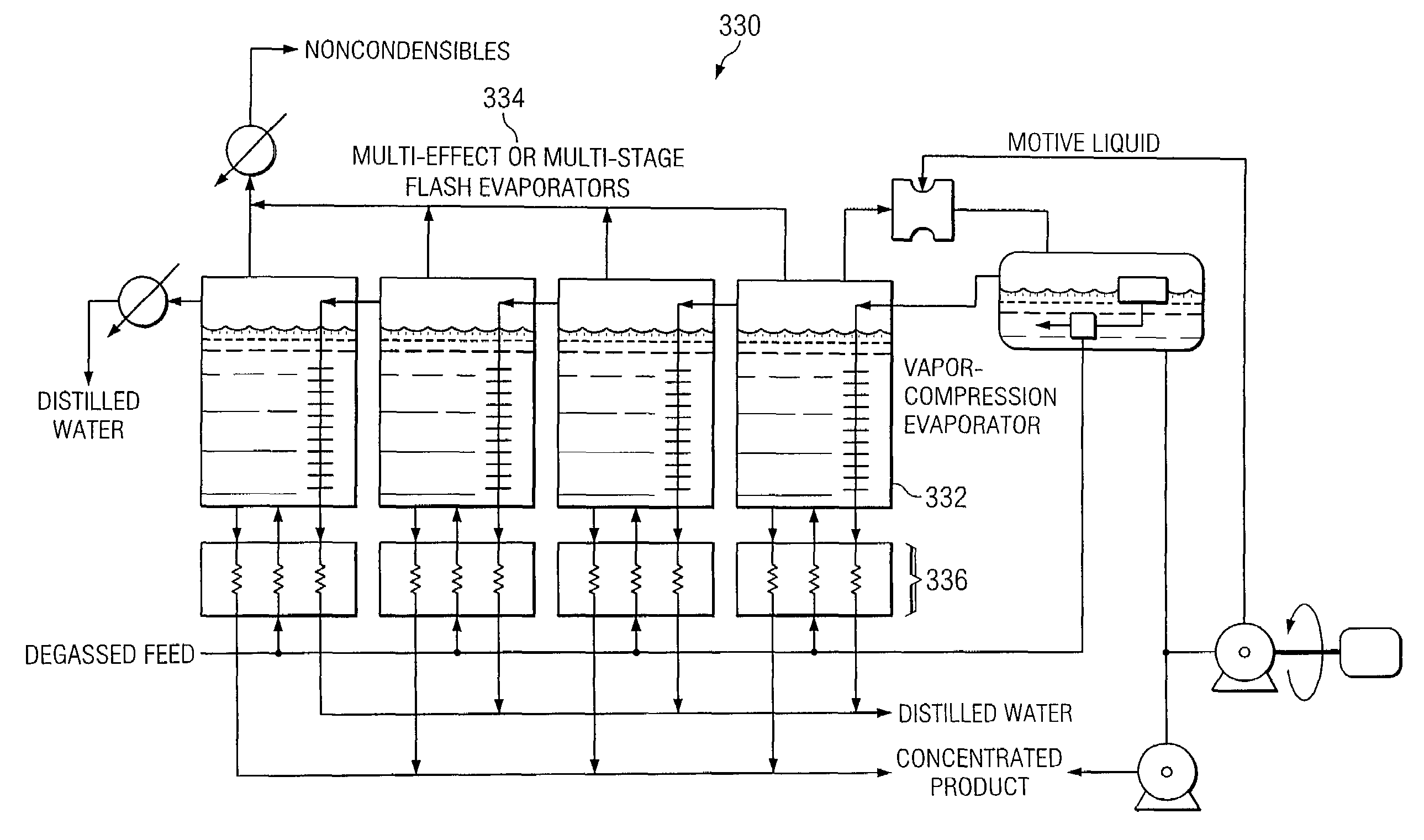
According to one embodiment of the invention, a vapor-compression evaporation system includes a plurality of vessels in series each containing a feed having a nonvolatile component, a mechanical compressor coupled to the last vessel in the series and operable to receive a vapor from the last vessel in the series, a pump operable to deliver a cooling liquid to the mechanical compressor, a tank coupled to the mechanical compressor and operable to separate liquid and vapor received from the mechanical compressor, a plurality of heat exchangers coupled inside respective ones of the vessels, the heat exchanger in the first vessel in the series operable to receive the vapor from the tank, at least some of the vapor condensing therein, whereby the heat of condensation provides the heat of evaporation to the first vessel in the series, and wherein at least some of the vapor inside the first vessel in the series is delivered to the heat exchanger in the next vessel in the series, whereby the condensing, evaporating, and delivering steps continue until the last vessel in the series is reached.

Description

RELATED APPLICATIONS[0001]This application claims the benefit of Ser. No. 60 / 504,138 titled “Jet Ejector System and Method,” filed provisionally on Sep. 19, 2003.TECHNICAL FIELD OF THE INVENTION[0002]The present invention relates generally to the field of jet ejectors and, more particularly, to an improved, ultra-high efficiency jet ejector system and method.BACKGROUND OF THE INVENTION[0003]Typical steam jet ejectors feed high-pressure steam, at relatively high velocity, into the jet ejector. Steam is usually used as the motive fluid because it is readily available; however, an ejector may be designed to work with other gases or vapors as well. For some applications, water and other liquids are sometimes good motive fluids as they condense large quantities of vapor instead of having to compress them. Liquid motive fluids may also compress gases or vapors.[0004]The motive high-pressure steam enters a nozzle and issues into the suction head as a high-velocity, low-pressure jet. The no...

Claims


Application Information

Patent Timeline
Patent Type & Authority Patents(United States)
IPC IPC(8): B01D1/26B01D1/28B01D3/00F04F5/46F04F5/54F28D9/00
CPCF04F5/466F28D9/0037F04F5/54F04F5/467Y10S203/08Y10S159/08
Inventor HOLTZAPPLE, MARK T.NOYES, GARY P.RABROKER, GEORGE A.
Owner TEXAS A&M UNIVERSITY
Learn More