Active sensor, multipoint active sensor, method for diagnosing deterioration of pipe, and apparatus for diagnosing deterioration of pipe, and apparatus for diagnosis deterioration of pipe

a multi-active sensor and active sensor technology, applied in the direction of instruments, nuclear elements, digital computer details, etc., can solve the problems of decreased availability factor, difficult to conduct the method during periodic inspection, and inability to be widely used, and achieve the effect of low manufacturing cos

Active Publication Date: 2010-05-04
KK TOSHIBA
View PDF7 Cites 45 Cited by
  • Summary
  • Abstract
  • Description
  • Claims
  • Application Information

AI Technical Summary

Benefits of technology

[0012]The present invention has been made in view of the above circumstances. The object of the present invention is to provide an active sensor, a multi-point active sensor, a method of diagnosing deterioration of a pipe, and an apparatus for diagnosing deterioration of a pipe, capable of inspecting, while a plant is running, a pipe over a wide area thereof for a short period of time, and of reducing the time and the number of steps required for the inspection, at a low manufacturing cost.
[0014]Due to this structure, there can be obtained, at a low manufacturing cost, a thin active sensor capable of simply inspecting a pipe while a plant is running, and of significantly reducing the time and the number of steps required for the inspection.
[0016]Due to this structure, there can be obtained, at a low manufacturing cost, a thin active sensor capable of simply inspecting a pipe while a plant is running, and of significantly reducing the time and the number of steps required for the inspection.
[0018]Due to this structure, the thickness of the pipe can be measured and mapped over a wider area, whereby the malfunction of the pipe can be accurately detected.
[0020]Due to this structure, the thickness of the pipe can be measured and mapped over a wider area, whereby the malfunction of the pipe can be accurately detected.
[0025]According to the present invention, by using an active sensor including an oscillator capable of inputting oscillatory waves into a pipe and scanning a frequency of the oscillatory waves within a desired range, and an optical fiber sensor mounted on the pipe, the optical fiber sensor detecting the oscillatory waves generated in the pipe, the pipe can be inspected over a wide area thereof for a short period of time at a low manufacturing cost, while a plant is running.

Problems solved by technology

However, in the above ultrasonic flaw detecting method, it is necessary to measure the thickness of a pipe at not less than 1000 positions, and thus it is difficult to conduct the method during a periodic inspection.
Further, when the thickness of the pipe is measured, it is necessary to stop the plant in consideration of a temperature constraint, which results in decrease in availability factor.
On the other hand, in the X-ray method capable of detecting a malfunction through the heat insulation member of the pipe, although the method can measure a distribution of the thickness of the pipe, the method is not widely used because an apparatus therefor is expensive.

Method used


Image

  • Active sensor, multipoint active sensor, method for diagnosing deterioration of pipe, and apparatus for diagnosing deterioration of pipe, and apparatus for diagnosis deterioration of pipe
  • Active sensor, multipoint active sensor, method for diagnosing deterioration of pipe, and apparatus for diagnosing deterioration of pipe, and apparatus for diagnosis deterioration of pipe
  • Active sensor, multipoint active sensor, method for diagnosing deterioration of pipe, and apparatus for diagnosing deterioration of pipe, and apparatus for diagnosis deterioration of pipe

Examples


first embodiment

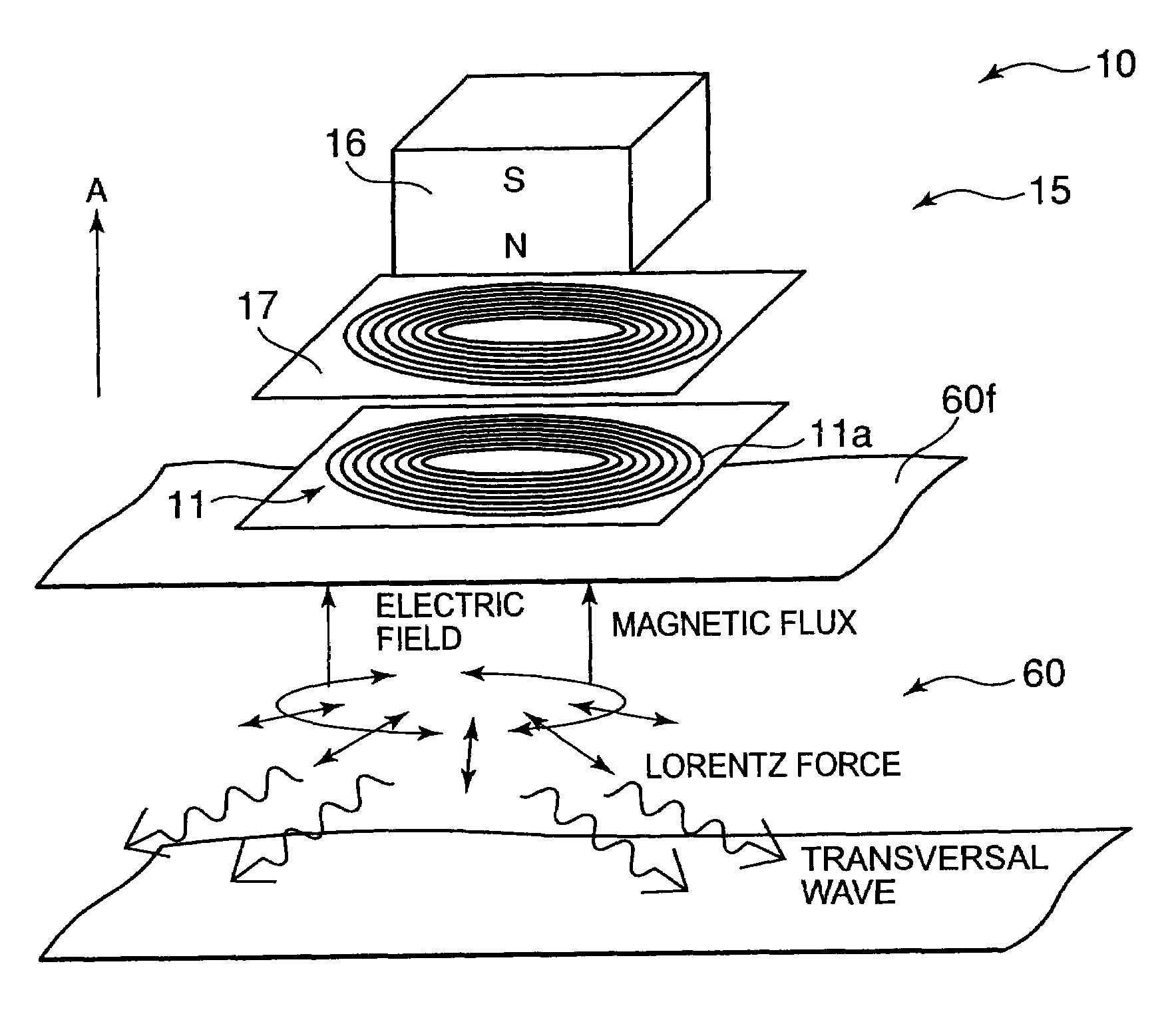
[0040]A first embodiment of an active sensor according to the present invention is described below, with reference to the drawings. FIGS. 1 to 8, FIGS. 13(a) and 13(b), and FIG. 14 are views showing the first embodiment of the present invention.

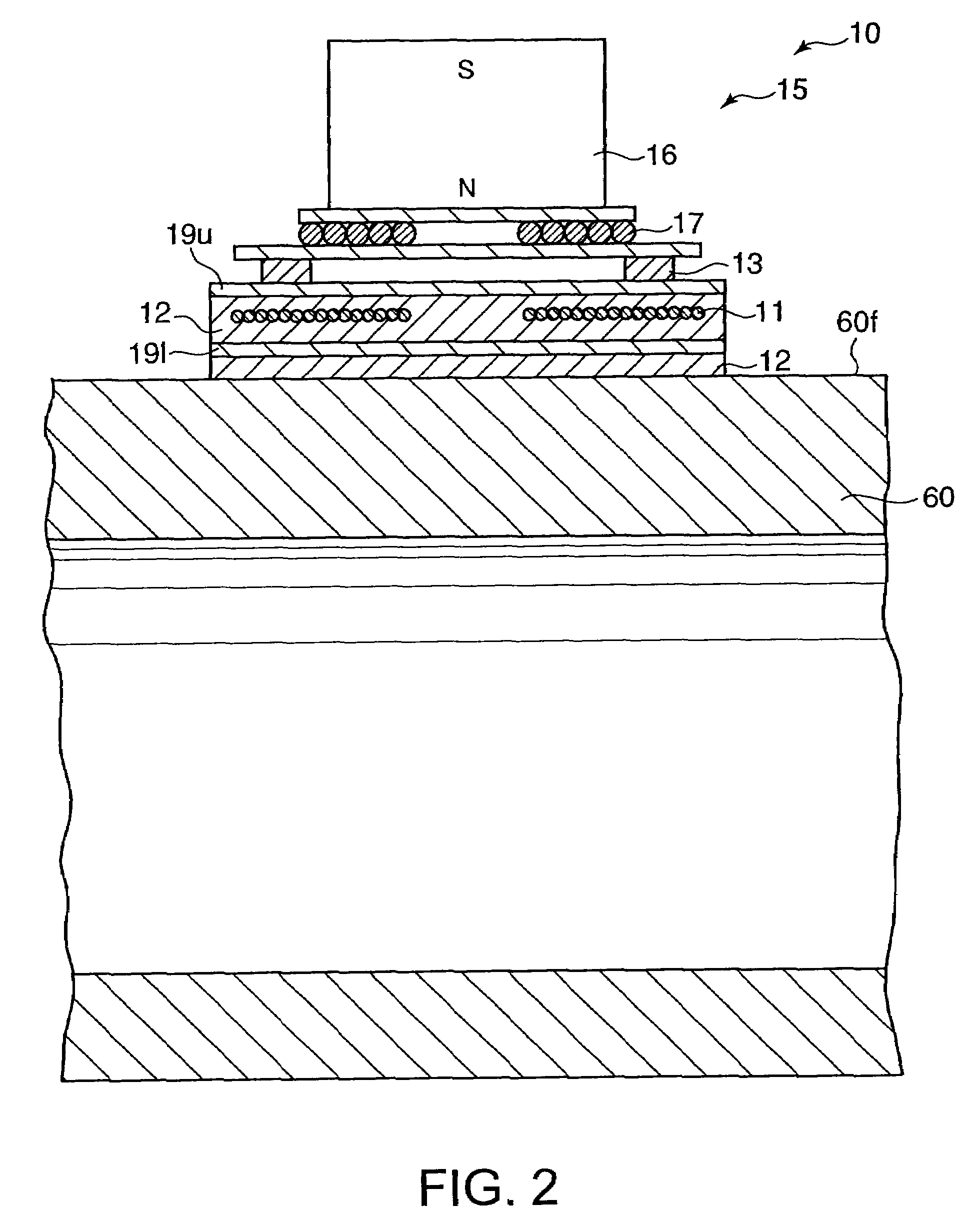
[0041]As shown in FIGS. 1 and 2, an active sensor 10 is positioned on an outside of a pipe 60, and is used for detecting a thickness of the pipe 60. The active sensor 10 has: an oscillator 15 capable of inputting oscillatory waves (ultrasonic waves) into the pipe 60 and scanning frequencies of the oscillatory waves within a desired range; and an optical fiber sensor 11 mounted on the oscillator 15 on a side of the pipe 60, the optical fiber sensor detecting the oscillatory waves generated in the pipe 60.

[0042]As shown in FIG. 2, the optical fiber sensor 11 is embedded in a high-temperature adhesive 12 filling a space between a pair of polyimide sheets 19u and 19l. The polyimide sheet 191, which is located on a lower part of FIG. 2, is attache...

example 1

Alternative Example 1

[0092]Next, an alternative example 1 of the first embodiment is described with reference to FIGS. 9(a) to 9(c). In the alternative example 1 of the first embodiment shown in FIGS. 9(a) to 9(c), in place of using the multi-point active sensor 20 in which the plurality of active sensors 10 are linearly arranged, there is used a multi-point active sensor 20 in which the plurality of active sensors 10 are arranged in matrix. Other structures of the alternative example 1 are substantially the same as those of the first embodiment shown in FIGS. 1 to 8.

[0093]In the alternative example 1 shown in FIGS. 9(a) to 9(c), the same parts as those in the first embodiment shown in FIGS. 1 to 8 are shown by the same reference numbers, and a detailed description thereof is omitted.

[0094]As shown in FIG. 9(b), the multi-point active sensor 20 in this embodiment has the plurality of active sensors 10 arranged in matrix. To be more specific, as shown in FIG. 9(b), in the multi-point...

example 2

Alternative Example 2

[0100]Next, an alternative example 2 of the first embodiment is described with reference to FIG. 10 and FIGS. 11(a) and 11(b). In the alternative example 2 shown in FIG. 10 and FIGS. 11(a) and 11(b), in place of using the oscillator 15 including the permanent magnet 16 positioned so as to generate a magnetic flux in a normal line direction of the pipe surface 60f (in the A direction shown by the arrow in FIG. 10) and the electric coil 17 disposed on the permanent magnet 16 on a side of the optical fiber sensor 11, there is used an oscillator 15 including a pair of permanent magnets 16 positioned so as to generate a magnetic flux in a direction perpendicular to a normal line direction of the pipe surface 60f (in the A direction shown by the arrow in FIG. 10), and an electric coil 17 disposed between the pair of permanent magnets 16. Other structures of the alternative example 2 are substantially the same as those of the first embodiment shown in FIGS. 1 to 8.

[010...


PUM


Abstract

An active sensor 10 is positioned on an outside of a pipe 60 so as to detect a thickness of the pipe. The active sensor comprises: an oscillator 15 capable of inputting oscillatory waves into the pipe and sweeping a frequency of the oscillatory waves within a desired range; and an optical fiber sensor mounted on the pipe, the optical fiber sensor detecting the oscillatory waves generated in the pipe.

Description

CROSS REFERENCE TO RELATED APPLICATIONS[0001]This application is based upon and claims the benefit of priority from the prior Japanese Patent Application No. 2007-106025 filed on Apr. 13, 2007, the entire contents of which are incorporated herein by reference.BACKGROUND OF THE INVENTION[0002]1. Field of the Invention[0003]The present invention relates to an active sensor, a multi-point active sensor, a method of diagnosing deterioration of a pipe, and an apparatus for diagnosing deterioration of a pipe, capable of judging existence of a malfunction such as a pipe wall-thickness reduction caused by a high-temperature steam in an atomic power plant and a heat power plant, and a pipe corrosion in a chemical factory and an incineration plant, and capable of identifying the part having a trouble.[0004]2. Description of Related Art[0005]A pipe wall-thickness reduction and a pipe corrosion are conventionally inspected on periodic inspections by using an ultrasonic flaw detecting method and...

Claims


Application Information

Patent Timeline
Patent Type & Authority Patents(United States)
IPC IPC(8): G02B6/00G01B11/02G21C17/017
CPCG01B17/02G01N29/043G01N29/07G01N29/2412G01N29/2418G01N29/348G21C17/017G01N2291/0258G01N2291/02854G01N2291/044G01N2291/2634
Inventor TAKAHASHI, MASASHISASAKI, KEIICHIYAMAGA, NOBUOAHIKO, NORIOYOSHIMURA, KOICHIOHI, MASANOBUMOCHIDA, YOSHIOMACHIJIMA, YUUICHISHIRAI, TAKEHIRO
Owner KK TOSHIBA
Why Eureka
Try Eureka