Fixed pitch continuously variable transmission (FPCVT)

a continuously variable transmission and fixed pitch technology, applied in the direction of gearing, gearing elements, hoisting equipment, etc., can solve the problems of impractical performance-oriented motoring, drive trains with higher horsepower ratings are not able to easily use these designs, and require outside control to shift ratios

Inactive Publication Date: 2010-05-11
HAWTHORN KENNETH B
View PDF6 Cites 65 Cited by
  • Summary
  • Abstract
  • Description
  • Claims
  • Application Information

AI Technical Summary

Benefits of technology

[0005]It is an object of the present invention to provide a CVT capable staying positively engaged to transmit power while allowing for continuous changes in ratio. Additionally the CVT design allows for automatic ratio selection based on the difference between power and load based on the mechanical specifications used in the design of the CVT, requiring no outside control input. The CVT consists of one or more Fixed Pitch Continuously Variable Transmission (FPCVT) units each having one spindle for power input and one spindle connected to the load. These two spindles are mounted so one may rotate freely around the other and share the same axis of rotation. These two spindles each have the same number of slots cut radially. One of the two spindles has these slots so cut at a different angle or curvature than the other. One pin intersects each set of slots and has mounted on it a combination of either all idler pulleys or idler pulleys and a sprocket to transmit the power to a chain. Rotating ether spindle relative to the other will cause the pins to force a pitch diameter change of the CVT assembly and the chains mounted on each pitch line. Only one sprocket is mounted on any one pitch line on any one FPCVT, thus allowing for a ratio changes while the CVT stays engaged. The sprockets are allowed to freely spin in either direction unless a roller chain or belt has fully seated on at least one tooth profile. The spindles share a set of springs that act to return the transmission to a higher ratio at moments the load is overcome.

Problems solved by technology

Drive trains with higher horsepower ratings are not able to easily use these designs as they rely on friction to transmit power and their size, weight and sensitivity to dirt make them impractical for performance oriented motoring.
The Anderson CVT exhibits these qualities, but requires the use of Floating Sprocket Bars that do not reengage smoothly and require outside control to shift ratios.

Method used


Image

  • Fixed pitch continuously variable transmission (FPCVT)
  • Fixed pitch continuously variable transmission (FPCVT)
  • Fixed pitch continuously variable transmission (FPCVT)

Examples


Embodiment Construction

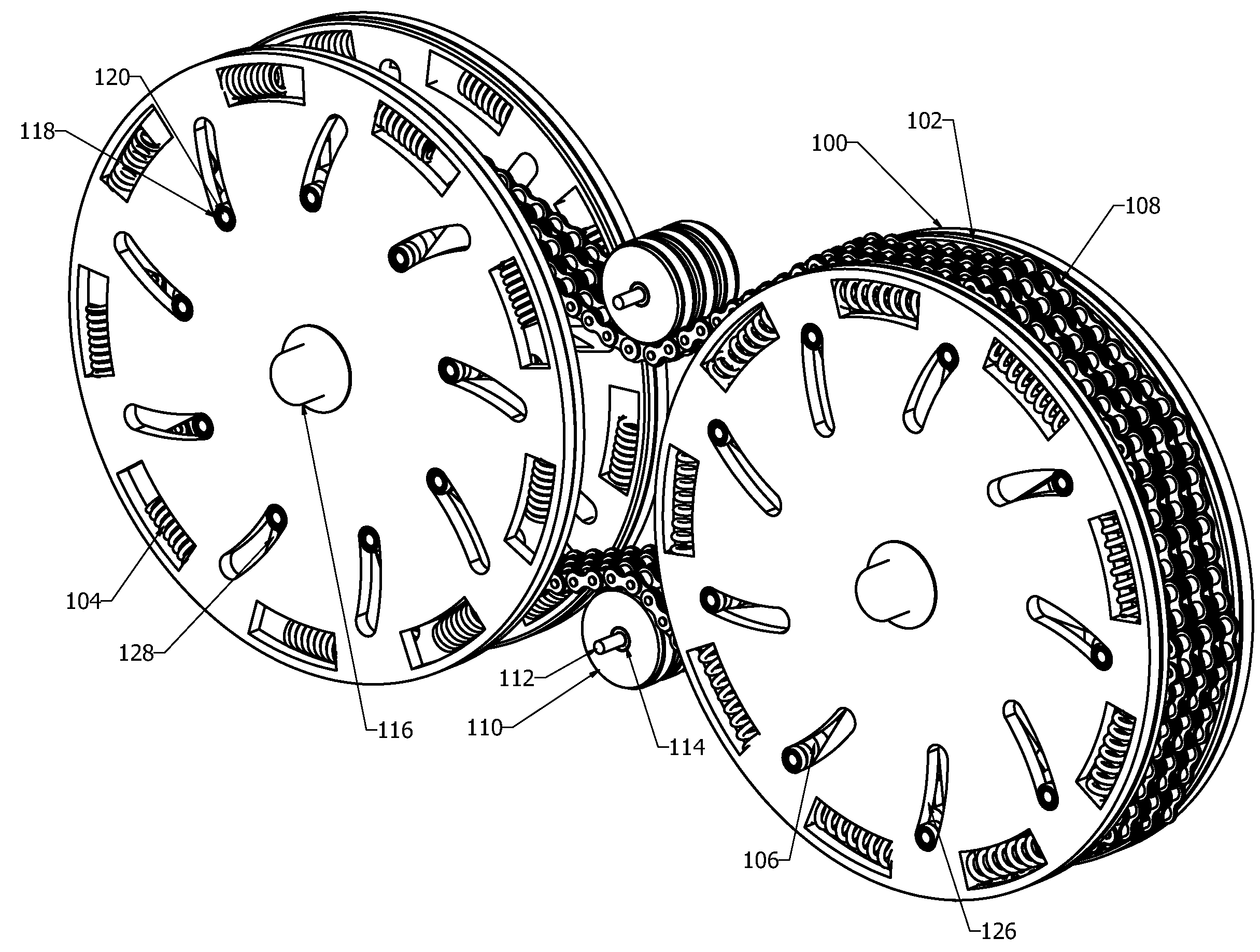
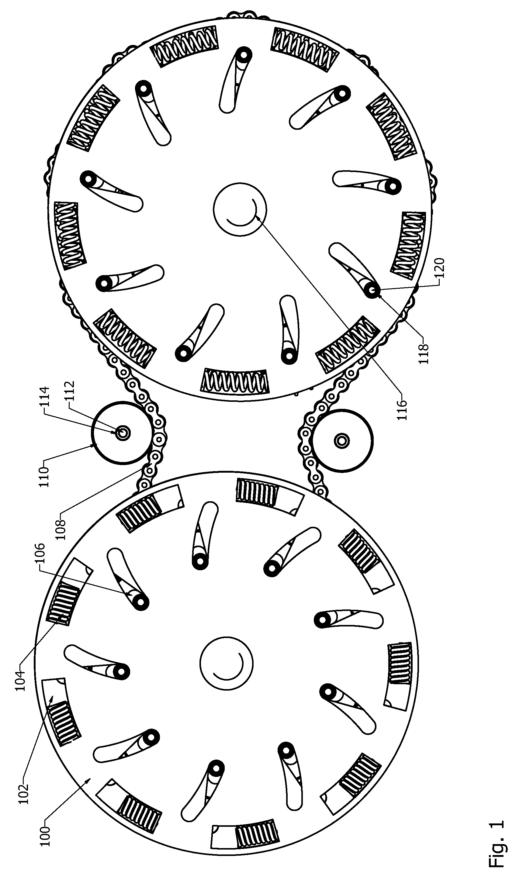
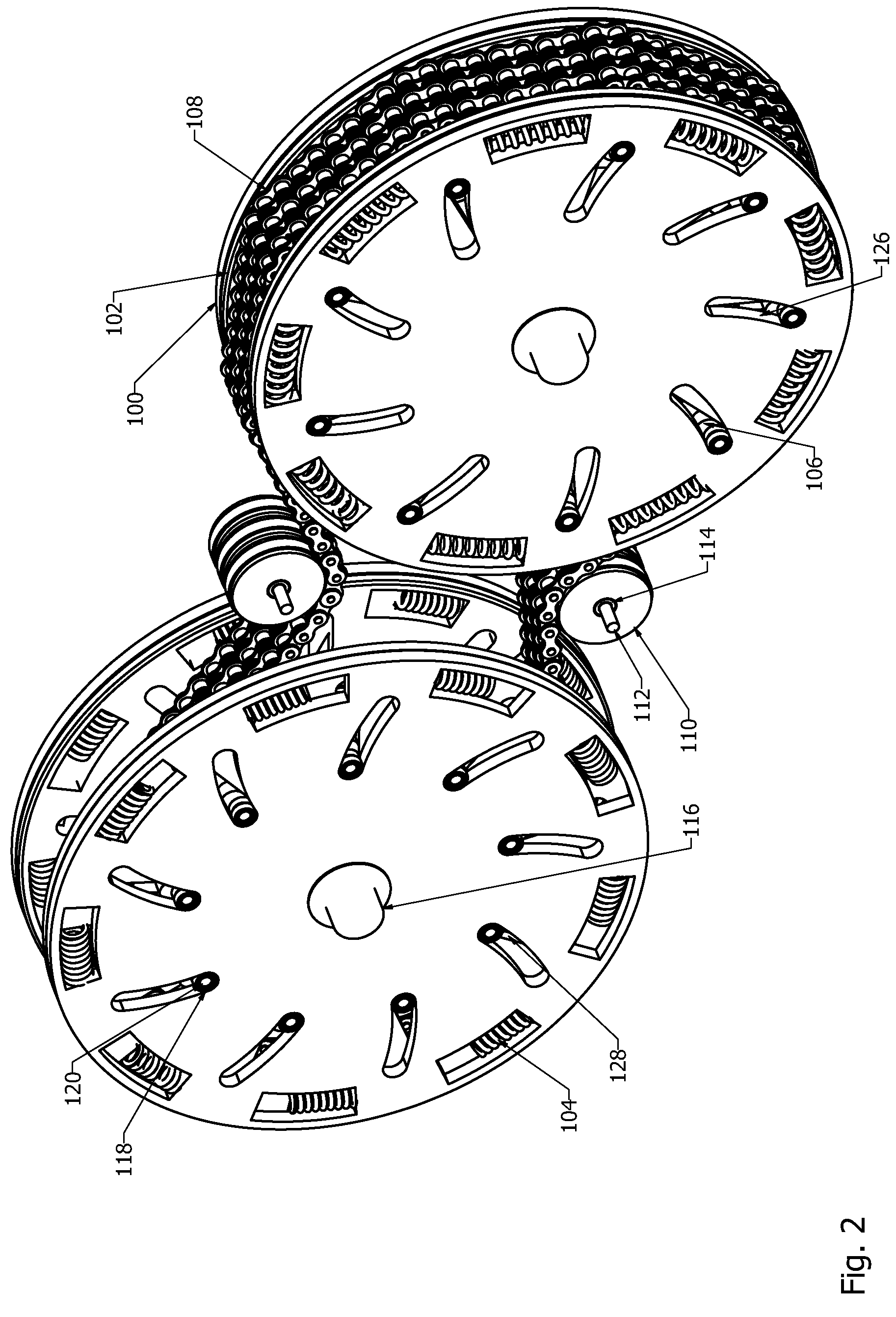
[0019]Referring now to drawings, in FIG. 1 the CVT is constructed with two identical Fixed Pitch Continuously Variable Transmission (FPCVT) assemblies. Referring now to FIG. 2 the two assemblies are connected by three roller chains 108. Referring to FIG. 3 the two assemblies shown in FIG. 2 are each comprised of: spindle 102 mounted inside spindle 100 sharing the same main axis of rotation and free to rotate around that main axis. Of the identical FPCVT assemblies shown in FIG. 1 and FIG. 2 keyway 136, shown in FIG. 3., on the right hand side FPCVT unit is connected to an engine or motor output shaft. Keyway 136 on the left hand side FPCVT unit is connected to the load. Spindle 100 is mounted via bearings to hard points of the transmission case via bearing mount 116. Nine slots 126 are cut radially though both faces of spindle 100. Nine slots 128 are cut radially though both faces of spindle 102, but at an angle and curvature relative to slots 126. One pin 120 intersects each pair o...


PUM


Abstract

A Continuously Variable Transmission (CVT) for use in applications where a transmission is desired to change the speed of the motor relative to the speed of the final drive. The CVT has a set of chains or belts that are mounted around a set of pins set in radially cut slots of a set of spindles so that the pattern of pins are able to expand and contract radially around the CVT axis via these slots. Sprockets that freely spin in either direction unless a chain or belt has fully seated on at least one tooth are arranged on the pins so that only one sprocket engages one chain or belt allowing for smooth ratio changes while the load in engaged. The spindles share a set of springs that act to return the transmission to a higher ratio at moments the load is overcome.

Description

BACKGROUND OF THE INVENTION[0001]1. Field of the Invention[0002]The present invention relates to Continuously Variable Transmissions (CVT's) used in a wide variety of applications requiring ratio shifts between an engine, or motor, and the load including automobiles, recreational vehicles, turbines and industrial equipment.[0003]2. Description of the Prior Art[0004]In recent years CVT's have become more widely adopted in the automotive industry in a never ending effort to increase fuel efficiency and increase performance. The most widely accepted automotive CVT's today are the Push Belt CVT marked by Nissan and General Motors and NSK half toroidal CVT. Drive trains with higher horsepower ratings are not able to easily use these designs as they rely on friction to transmit power and their size, weight and sensitivity to dirt make them impractical for performance oriented motoring. Other designs have come to market for smaller horsepower applications like the NuVinci CVP. There is gen...

Claims


Application Information

Patent Timeline
Patent Type & Authority Patents(United States)
IPC IPC(8): F16H9/10
CPCF16G13/06F16H9/24F16H9/10
Inventor HAWTHORN, KENNETH B.
Owner HAWTHORN KENNETH B
Why Eureka
Try Eureka