Power storage device

a power storage device and power technology, applied in the direction of resonant antennas, electric generators, transportation and packaging, etc., can solve the problems of increasing volume and weight of devices, increasing the structural difficulty of downsizing power storage devices, and increasing the weight of devices, so as to prolong the life of power storage devices, improve rigidity, and maintain durability and required functions

Inactive Publication Date: 2010-05-11
SEMICON ENERGY LAB CO LTD
View PDF20 Cites 239 Cited by
  • Summary
  • Abstract
  • Description
  • Claims
  • Application Information

AI Technical Summary

Benefits of technology

[0008]Incidentally, in the field of portable electronic devices in the future, portable electronic devices will be desired, which are smaller and more lightweight and can be used for a long time period by one-time charging, as apparent from provision of one-segment partial reception service “1-seg” of terrestrial digital broadcasting that covers the mobile objects such as a cellular phone. Therefore, the need for the power storage device is increased, which is small and lightweight and capable of being charged without receiving power from commercial power.
[0009]It is an object of the present invention to provide a power storage device that can be charged without receiving power from commercial power, in which the charging is performed easily while reduction in size and weight or reduction in weight and thickness is achieved. It is another object of the present invention to maintain durability and required functions in the case where such a power storage device becomes small and downsized.
[0012]According to the present invention, a circuit for storing power of an electromagnetic wave received at an antenna in a capacitor and a control circuit for discharging the given power are provided, whereby lifetime of the power storage device can be extended.
[0013]When the structural body formed of ceramics or the like is used for part of the power storage device, rigidity can be improved. Accordingly, even when the power storage device is thinned, durability and required functions can be maintained.
[0014]For example, even when pressing force is applied with a pointed object such as a tip of a pen, malfunction due to stress applied to the capacitor and the control circuit can be prevented. Moreover, resistance to bending stress can also be provided. In addition, when a wiring for connection is formed in the structural body formed of ceramics or the like so that the antenna and the control circuit are connected, malfunction caused by detachment of a connection portion can be prevented even when bending stress is applied.

Problems solved by technology

However, the power storage device utilizing electromagnetic induced electromotive force generated by a coil and a permanent magnet needs a movable portion, and therefore, downsizing of the power storage device is structurally difficult.
Moreover, such a power storage device is required to move the magnet as well as to possess it, and the weight of the device is increased because the permanent magnet is used.
Therefore, the conventional power storage device has a problem that the volume and the weight thereof are increased, and portability is lost.

Method used


Image

  • Power storage device
  • Power storage device
  • Power storage device

Examples


embodiment 1

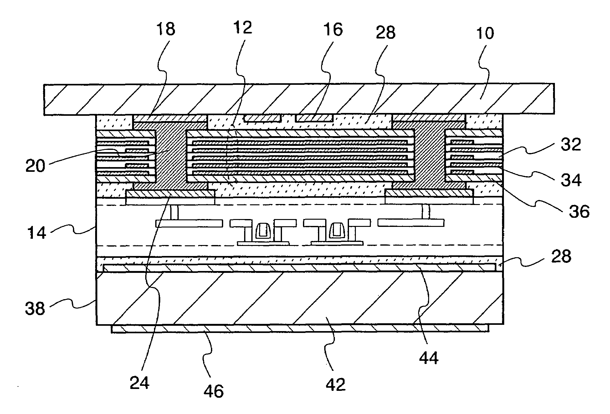
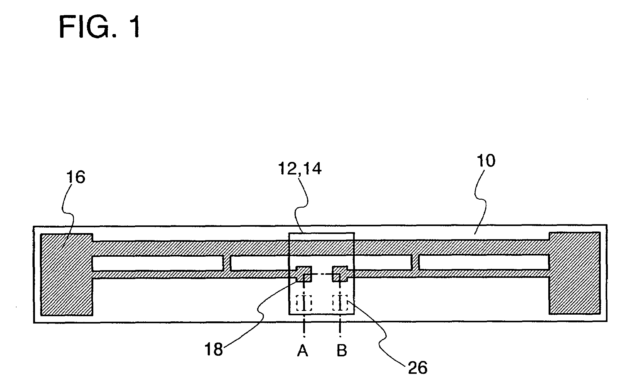
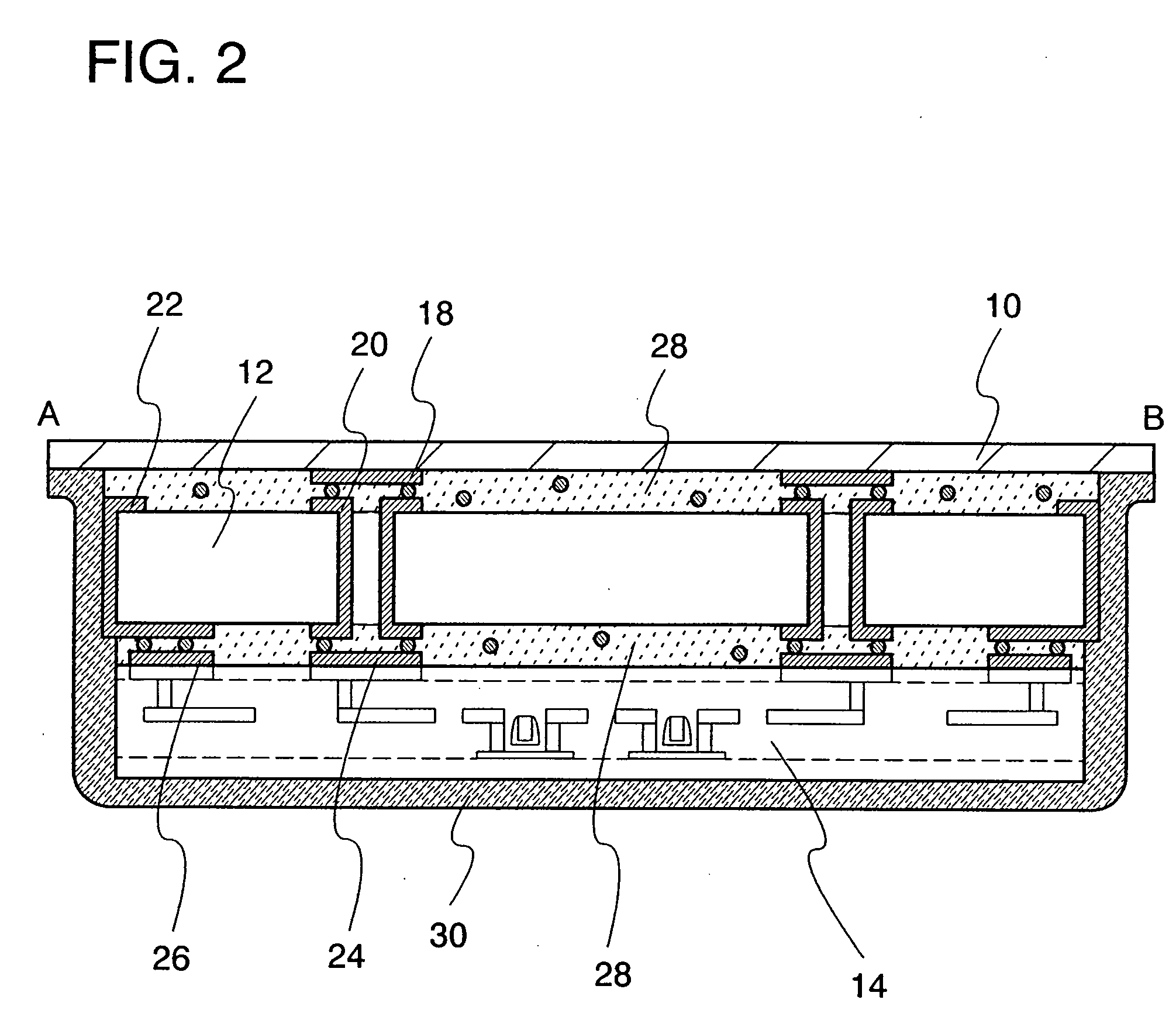
[0050]This embodiment will explain an example of a power storage device that includes a first structural body provided with an antenna, a second structural body provided with a capacitor, and a power supply control circuit 14, with reference to FIGS. 4A to 4C and FIGS. 5A and 5B. FIGS. 4A to 4C are plan views of the power storage device, and FIGS. 5A and 5B are cross-sectional views taken along lines A-B and C-D of FIG. 4A.

[0051]FIG. 4A shows a mode in which an antenna 16 having a coil-shape is formed in a first structural body 10. The first structural body 10 is formed using a plastic material such as PET (polyethylene terephthalate), PEN (polyethylene naphthalate), PES (polyethersulfone), polypropylene, polypropylene sulfide, polycarbonate, polyether imide, polyphenylene sulfide, polyphenylene oxide, polysulfone, polyphthalamide, acrylic, or polyimide, or an insulating material such as nonwoven fabric, or paper.

[0052]The antenna 16 is formed in the first structural body 10 using a...

embodiment 2

[0060]This embodiment will explain an example of a power storage device of the present invention provided with a plurality of antennas. An example of a power storage device will be explained with reference to FIGS. 6A to 6D and FIGS. 7A and 7B, which includes a first structural body 10 provided with an antenna, a second structural body 12 provided with a capacitor, a power supply control circuit 14, and a ceramics antenna 38. FIGS. 6A to 6D are plan views of the power storage device, and FIGS. 7A and 7B are cross-sectional views taken along lines E-F and G-H.

[0061]In FIG. 6A, an antenna 16 having a coil-shape is formed in the first structural body 10. The shape of the antenna 16 may be appropriately set in accordance with a frequency band that is used for communication, similarly to in Embodiment 1.

[0062]FIG. 6A shows a mode in which the second structural body 12, the power supply control circuit 14, and the ceramics antenna 38 are provided in accordance with an antenna terminal 18....

embodiment 3

[0068]An example of a power supply control circuit of a power storage device of the present invention will be explained with the use of a block diagram shown in FIG. 8.

[0069]A power storage device 100 of FIG. 8 includes an antenna 102, a power supply control circuit 104, and a capacitor 106. The power supply control circuit 104 includes a rectifier circuit 108, a low-frequency signal generation circuit 110, a switching circuit 112, and a power supply circuit 114. Power is output from the power supply circuit in the power supply control circuit to a load 118 on the outside of the power storage device.

[0070]The antenna 102 is formed in the first structural body 10 in accordance with Embodiment 1. The capacitor 106 is formed in the second structural body 12. The power supply control circuit 104 corresponds to the power supply control circuit 14.

[0071]A structure of the load 118 in FIG. 8 is different depending on electronic devices. For example, in the cellular phones and the digital v...


PUM

PropertyMeasurementUnit
thicknessaaaaaaaaaa
thicknessaaaaaaaaaa
frequencyaaaaaaaaaa

Abstract

In the field of portable electronic devices in the future, portable electronic devices will be desired, which are smaller and more lightweight and can be used for a long time period by one-time charging, as apparent from provision of one-segment partial reception service “1-seg” of terrestrial digital broadcasting that covers the mobile objects such as a cellular phone. Therefore, the need for a power storage device is increased, which is small and lightweight and capable of being charged without receiving power from commercial power. The power storage device includes an antenna for receiving an electromagnetic wave, a capacitor for storing power, and a circuit for controlling store and supply of the power. When the antenna, the capacitor, and the control circuit are integrally formed and thinned, a structural body formed of ceramics or the like is partially used. A circuit for storing power of an electromagnetic wave received at the antenna in a capacitor and a control circuit for arbitrarily discharging the stored power are provided, whereby lifetime of the power storage device can be extended.

Description

BACKGROUND OF THE INVENTION[0001]1. Field of the Invention[0002]The present invention relates to a power storage device capable of being charged without receiving power from commercial power.[0003]2. Description of the Related Art[0004]Electronic devices such as a cellular phone, a mobile computer, a digital camera, and a digital audio player have been advanced to be downsized, and a large variety of products have been shipped to the market. In such portable electronic devices, a secondary battery as a power supply for driving is incorporated. As a secondary battery, a lithium-ion battery, a nickel-hydrogen battery, or the like is used. The secondary battery is charged by receiving power from commercial power. For example, a user connects an AC adapter to a household plug socket deposited in each home to charge the secondary battery.[0005]Although portable electronic devices are convenient, the hour of use is restricted by the capacity of the secondary battery. The user of the elect...

Claims


Application Information

Patent Timeline
Patent Type & Authority Patents(United States)
IPC IPC(8): H01M10/46H02J7/00H01Q1/38H01Q7/00H01Q9/28
CPCH01Q1/36H01Q1/38H01L27/0629H01Q9/285H02J17/00H01Q7/00H02J50/005H02J50/27H02J50/12H02J50/50H02J50/10
Inventor YAMAZAKI, SHUNPEIARAI, YASUYUKI
Owner SEMICON ENERGY LAB CO LTD
Why Eureka
Try Eureka