
Solution-dependent regularization method for quantizing continuous-tone lithography masks

Active Publication Date: 2010-05-11
D2S
View PDF12 Cites 34 Cited by
  • Summary
  • Abstract
  • Description
  • Claims
  • Application Information

AI Technical Summary

Benefits of technology

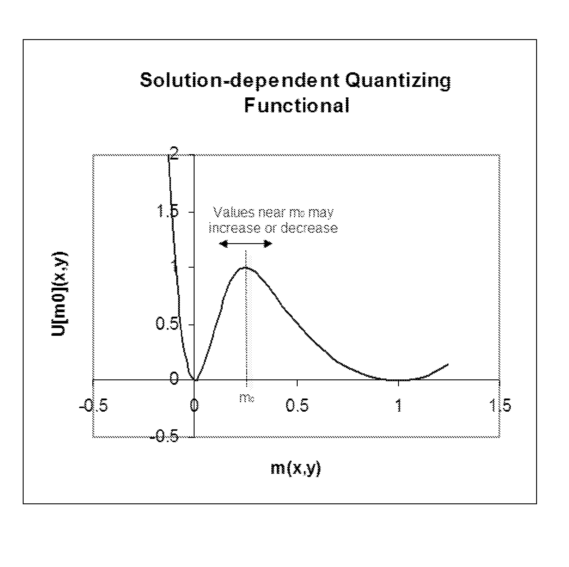
[0013]In one embodiment, the invention undertakes multiple steps where the quantizing functional becomes a larger fraction of the total cost functional and where the hills placed underneath intermediate values are adjusted to chase them to any allowed value. The mask function is thus brought to quantized values in a controlled and optimal way.

Problems solved by technology

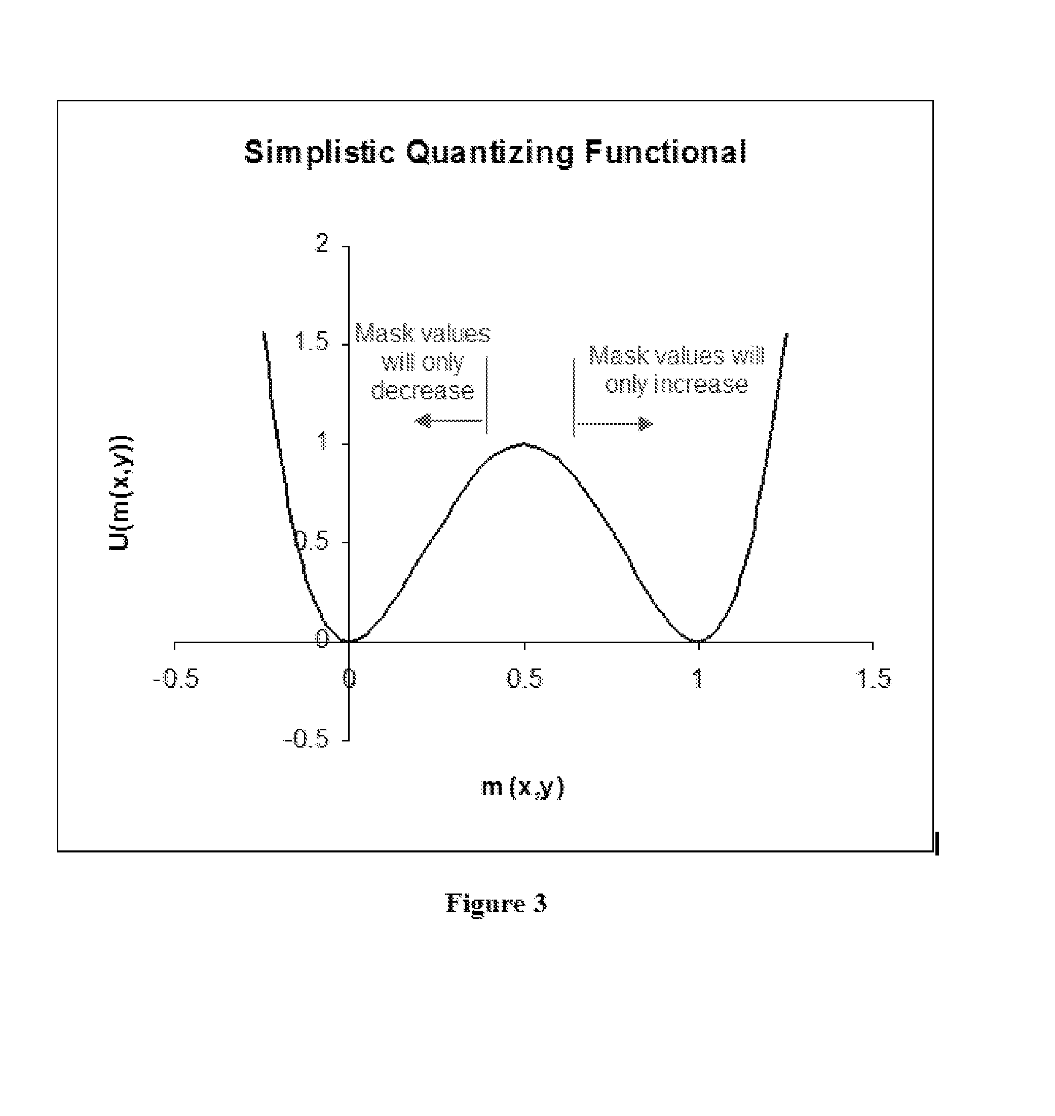
In one embodiment, a cost functional term places a cost maximum locally at intermediate current mask values so they will be unstable and tend to “roll” downhill towards an allowed value on either side of the hill.

Method used


Image

  • Solution-dependent regularization method for quantizing continuous-tone lithography masks
  • Solution-dependent regularization method for quantizing continuous-tone lithography masks
  • Solution-dependent regularization method for quantizing continuous-tone lithography masks

Examples


Embodiment Construction

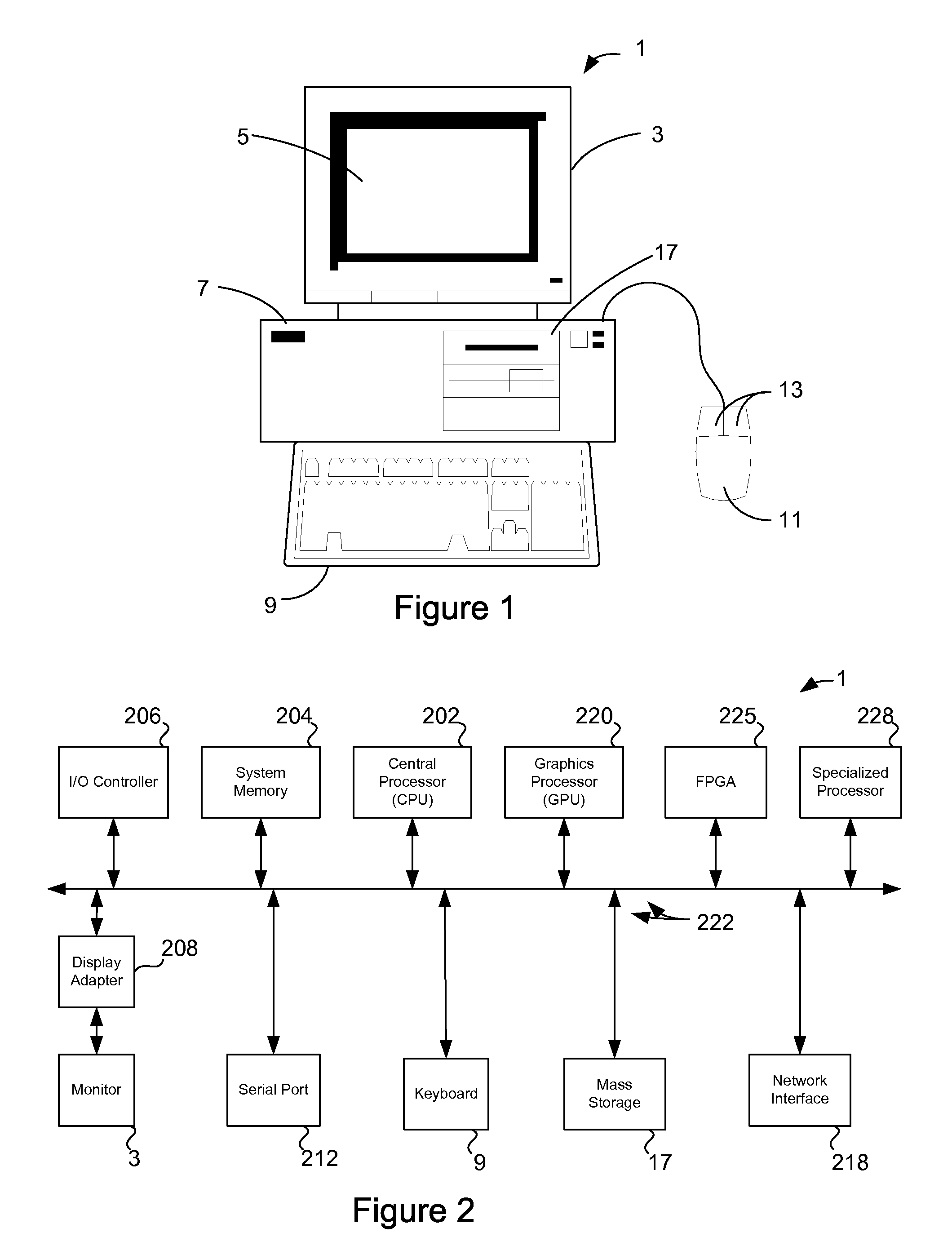
[0021]FIG. 1 shows a system of the present invention. In an embodiment, the invention is software that executes on a computer workstation system, such as shown in FIG. 1. FIG. 1 shows a computer system 1 that includes a monitor 3, screen 5, cabinet 7, keyboard 9, and mouse 11. Mouse 11 may have one or more buttons such as mouse buttons 13. Cabinet 7 houses familiar computer components, some of which are not shown, such as a processor, memory, mass storage devices 17, and the like.

[0022]Mass storage devices 17 may include mass disk drives, floppy disks, magnetic disks, optical disks, magneto-optical disks, fixed disks, hard disks, CD-ROMs, recordable CDs, DVDs, recordable DVDs (e.g., DVD-R, DVD+R, DVD-RW, DVD+RW, HD-DVD, or Blu-ray Disc), flash and other nonvolatile solid-state storage (e.g., USB flash drive), battery-backed-up volatile memory, tape storage, reader, and other similar media, and combinations of these.

[0023]A computer-implemented or computer-executable version of the i...


PUM


Abstract

In an electronic design automation technique for optical proximity correction, an optimized mask function that has values other than those allowed for a particular mask type, such as 0 and 1 for a chrome-on-glass binary mask, evolves it to a solution restricted to these values or narrow intervals near them. The technique “regularizes” the solution by mixing in a new cost functional that encourages the mask to assume the desired values. The mixing in may be done over one or more steps or even “quasistatically,” in which the total cost functional and the mask is brought from pure goodness-of-fit to the printed layout for given conditions to pure manufacturability by keeping the total cost functional minimized step-by-step. A goal of this gradual mixing-in is to do thermodynamically optimal work on the mask function to bring it to manufacturable values.

Description

CROSS-REFERENCE TO RELATED APPLICATION[0001]This patent application claims the benefit of U.S. provisional patent application 60 / 827,295, filed Sep. 28, 2006, which is incorporated by reference along with all other references cited in this application.BACKGROUND OF THE INVENTION[0002]This invention relates to the field of electronic design automation, and in particular, improved techniques for photolithography mask design.[0003]Lithography mask optimization methods either force the mask to satisfy a priori mask manufacturability constraints at all times or use the “regularization” procedures of “inverse methods” to favor solutions that satisfy these constraints. More generally, there can be some constraints built into the mask representation or optimization algorithm and others handled through regularization procedures. Conceptually, an optimization algorithm can be more efficient in terms of speed and quality of solution by searching an unconstrained solution space, using regulariz...

Claims


Application Information

Patent Timeline
Patent Type & Authority Patents(United States)
IPC IPC(8): G06F17/20G06F40/00
CPCG03F1/50G06F17/50G03F1/70G03F1/28G06F30/00G06F30/39G06F30/398G06F2111/10G06F2119/18G03F1/00G06F17/14G21K5/00
Inventor UNGAR, P. JEFFREYTORUNOGLU, ILHAMI H.
Owner D2S
Learn More