Method of detecting and compensating for injector variability with a direct injection system

a direct injection and injector technology, applied in the direction of liquid fuel feeders, machines/engines, electric control, etc., can solve the problems of cylinder torque output imbalance, piece-to-piece and time-to-time variability of engine systems, and increase the emission of tail pipes, so as to reduce the temperature sensitivity of fuel rails, increase correlation results, and reduce pump operation

Active Publication Date: 2010-05-18
FORD GLOBAL TECH LLC
View PDF10 Cites 52 Cited by
  • Summary
  • Abstract
  • Description
  • Claims
  • Application Information

AI Technical Summary

Benefits of technology

[0007]Furthermore, by using a higher starting fuel rail pressure during the correlation, the fuel rail can be filled with fresher and colder fuel while the fuel injector is calibrated. This may reduce the fuel rail temperature sensitivity, and thus increase correlation results.
[0008]Finally, in an example where a predetermined number of injections for each injector in the engine are performed subsequent and proximate to the reduction in pump operation, it may be possible to avoid any torque imbalance produced when a single injector is disabled or the injection volume of a single injector is reduced.

Problems solved by technology

Fuel injectors of direct injection engine systems often have piece-to-piece and time-to-time variability, due to imperfect manufacturing processes and / or injector aging, for example.
This injector variability may cause cylinder torque output imbalance due to the different amount of fuel injected into each cylinder, and may also cause higher tail pipe emission and reduced fuel economy due to an inability to correctly meter the fuel to be injected into each cylinder.
For example, during a calibration injection event, the fuel rail pressure drop is monitored from a normal operating pressure to a lower threshold pressure, since the lower threshold pressure may be limited by the inability of injectors to accurately meter fuel below a certain pressure, the amount of pressure drop available for a given calibration injection event may therefore be limited.
In other words, the number and size of injections for a given calibration injection event may not be sufficient to accurately calibrate all injectors.
In addition to be above issue, the individual cylinder injector calibration using injector deactivation can result in undesirable air-fuel ratio excursions, un-even torque production from cylinder to cylinder, and increased engine vibration (such as during idle conditions).
Furthermore, when fuel rail pressure is maintained at normal operating pressures, a relatively small amount of fuel may be present in the fuel rail during calibration due to the relatively low fuel pressure.
As such, the small amount of fuel present in the fuel rail may increase fuel metering sensitivity to engine heat, which may in turn degrade calibration results.
This may reduce the fuel rail temperature sensitivity, and thus increase correlation results.

Method used


Image

  • Method of detecting and compensating for injector variability with a direct injection system
  • Method of detecting and compensating for injector variability with a direct injection system
  • Method of detecting and compensating for injector variability with a direct injection system

Examples


Embodiment Construction

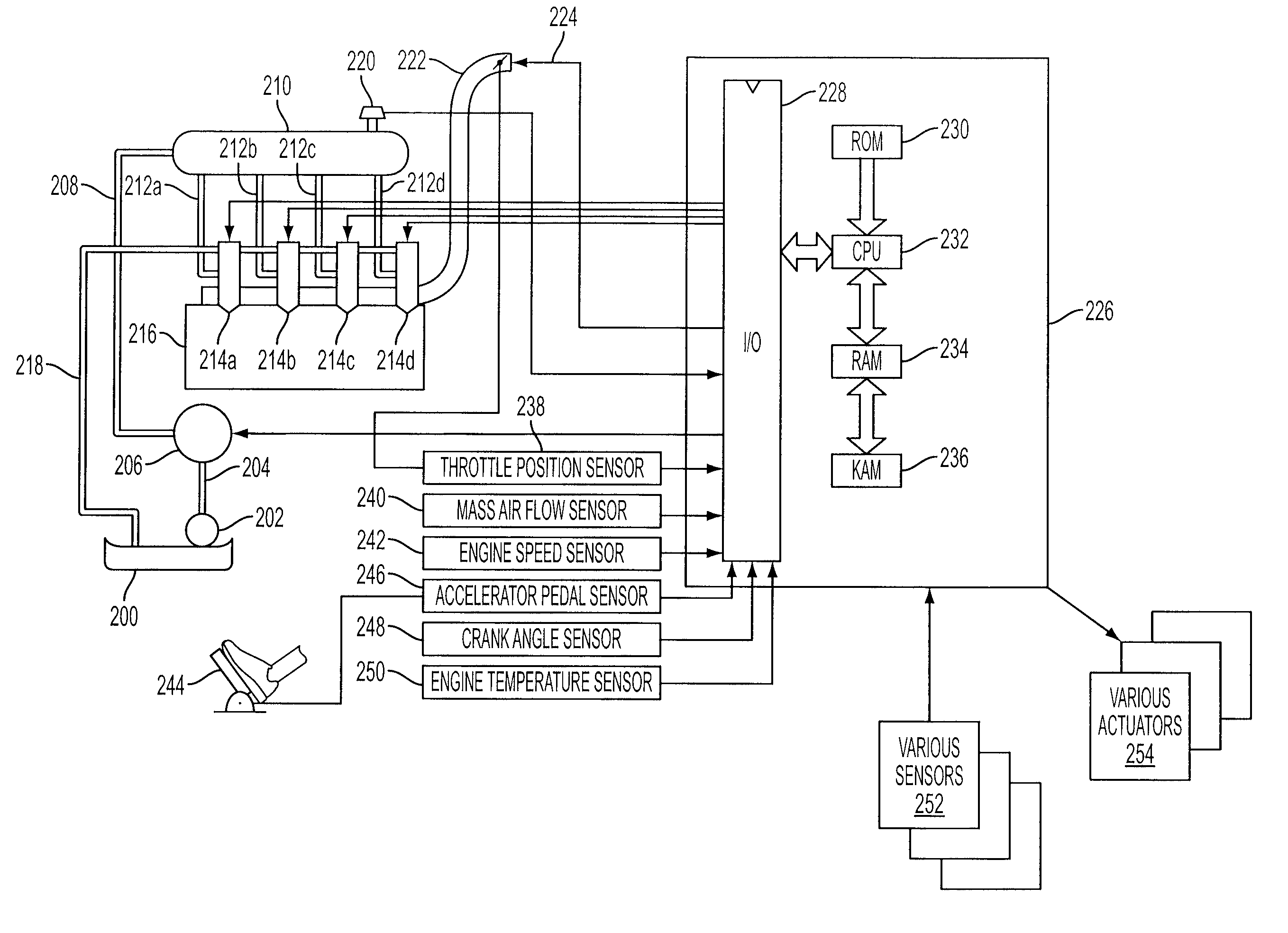
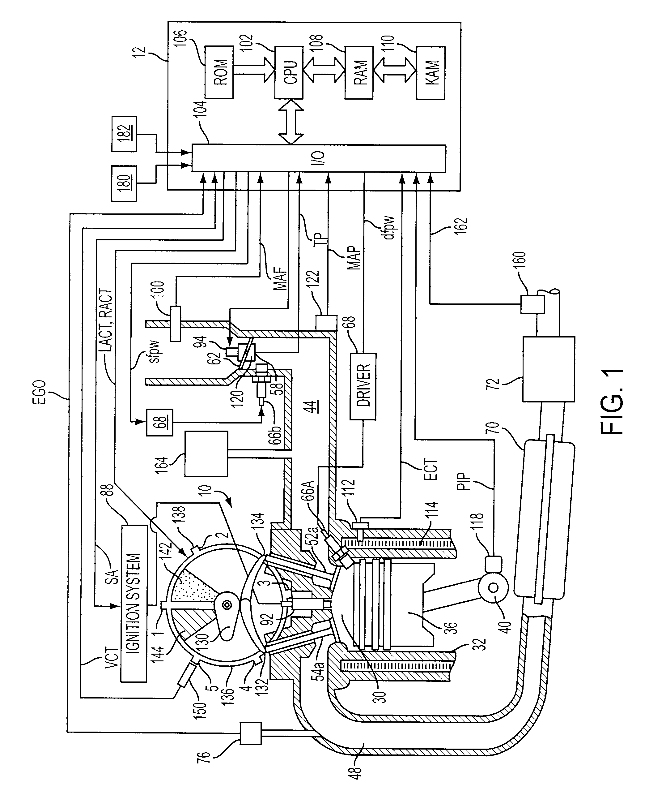
[0016]FIG. 1 shows one cylinder of a multi-cylinder engine, as well as the intake and exhaust path connected to that cylinder.

[0017]Continuing with FIG. 1, it shows a direct injection system, where engine 10 has direct fuel injection, as well as spark ignition. Internal combustion engine 10, comprising a plurality of combustion chambers, is controlled by electronic engine controller 12. Combustion chamber 30 of engine 10 is shown including combustion chamber walls 32 with piston 36 positioned therein and connected to crankshaft 40. A starter motor (not shown) may be coupled to crankshaft 40 via a flywheel (not shown), or alternatively direct engine starting may be used.

[0018]In one particular example, piston 36 may include a recess or bowl (not shown) to help in forming stratified charges of air and fuel, if desired. In some examples, a flat piston may be used.

[0019]Combustion chamber, or cylinder, 30 is shown communicating with intake manifold 44 and exhaust manifold 48 via respect...


PUM


Abstract

A method for controlling fuel injection of a direct injection fuel system, the fuel system having a fuel pump, the method comprising: variably operating the fuel pump to maintain a fuel pressure at a selected pressure, temporarily increasing pump operation to increase pressure sufficiently above said selected pressure and then reducing pump operation; during at least a fuel injection subsequent to the reduction in pump operation, correlating pressure decrease to injector operation, and adjusting fuel injection operation based on the correlation.

Description

BACKGROUND AND SUMMARY[0001]Fuel injectors of direct injection engine systems often have piece-to-piece and time-to-time variability, due to imperfect manufacturing processes and / or injector aging, for example. This injector variability may cause cylinder torque output imbalance due to the different amount of fuel injected into each cylinder, and may also cause higher tail pipe emission and reduced fuel economy due to an inability to correctly meter the fuel to be injected into each cylinder.[0002]To compensate for injector variability, correction coefficients that correct for injection parameters, such as injection time, may be used. For example, U.S. Pat. No. 5,176,122 discloses a method that utilizes both average correction coefficients and individual correction coefficients to correct for injector variability. To calibrate the average and individual correction coefficients, calibration injection events are carried out while the fuel supply is stopped during various conditions, s...

Claims


Application Information

Patent Timeline
Patent Type & Authority Patents(United States)
IPC IPC(8): F02M51/00F02M51/04
CPCF02D41/2438F02D41/2467F02D41/3845F02D41/0085F02D41/401F02D2041/224F02D2200/0602Y02T10/44Y02T10/40F02D41/3809F02D41/40
Inventor THOMAS, JOSEPH LYLE
Owner FORD GLOBAL TECH LLC
Why Eureka
Try Eureka