Supercharge Your Innovation With Domain-Expert AI Agents!

Method and apparatus for output amplifier protection

a protection device and output amplifier technology, applied in the direction of low frequency amplifiers, transducer casings/cabinets/supports, electrical transducers, etc., can solve the problems of two halves of signals, crossover distortion, mismatch drawback, etc., to reduce voltage drop, reduce voltage drop, the effect of reducing the voltage drop

Active Publication Date: 2010-05-18
NUVOTON
View PDF4 Cites 11 Cited by
  • Summary
  • Abstract
  • Description
  • Claims
  • Application Information

AI Technical Summary

Benefits of technology

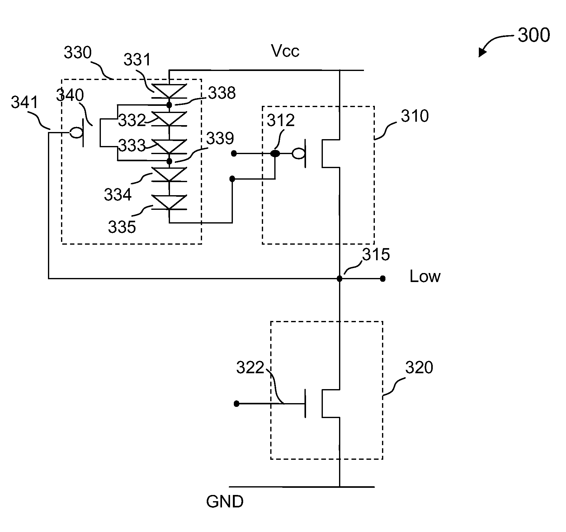
The present invention provides techniques for protecting an amplifier circuit against excess current conditions. The invention includes a protection circuit that limits the current flow when a circuit node is outside a certain voltage range. The protection circuit includes a plurality of serially connected diode devices that clamp the gate-to-source bias of a PMOS transistor when the voltage at the output node is outside a predetermined range. The invention can be applied to various types of amplifier circuits and can limit current flow in an internal circuit node in a desirable range. The technical effect of the invention is to provide a safer and more reliable amplifier circuit that can protect against short circuit conditions and overcurrent events.

Problems solved by technology

This arrangement gives improved efficiency, but can suffer from the drawback of mismatch at the “joins” between the two halves of the signal, also known as the crossover distortion.
Even though audio amplifier circuits are widely used in many applications, certain limitations still exist.
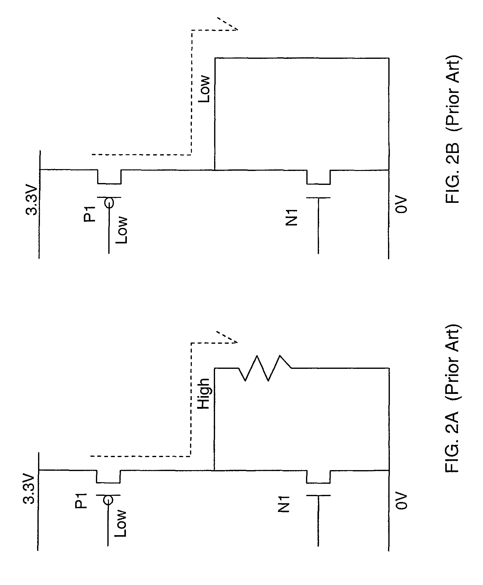
If the output node is shorted to ground, the current can be very large.
This large current flow can cause damages to the audio system.
Conventional output protection techniques are often ineffective or expensive.
However, this approach has several drawbacks, including additional circuitry, more chip area, and power consumption.
However, this method can lead to degradation of system performance.

Method used


Image

  • Method and apparatus for output amplifier protection
  • Method and apparatus for output amplifier protection
  • Method and apparatus for output amplifier protection

Examples


Embodiment Construction

[0037]The present invention relates generally to electronic circuit techniques. More specifically, embodiments of the present invention provide techniques for protecting an amplifier circuit against short circuit conditions. Merely by way of example, the invention has been applied to an integrated circuit including an audio power amplifier for protecting against short circuit at an output driver circuit. But it would be recognized that the invention has a much broader range of applicability. For example, the invention can be applied to other types of amplifier circuits to limit the current flow in a desirable range.

[0038]Depending upon the embodiment, the present invention includes various features, which may be used. These features include the following:[0039]1. Provide techniques for protecting an amplifier circuit using a protection circuit having a stack of diode devices in an output driver;[0040]2. Provide a design of the protection circuit that is activated by a pre-selected c...


PUM


Abstract

An amplifier circuit includes a first circuit and a second circuit connected in series. The first circuit has a first terminal coupled to a first power supply terminal, a second terminal coupled to an output node, and a control terminal for receiving a first signal for controlling a current flow. The second circuit has a first terminal coupled to the output node, a second terminal couple to a second power supply terminal, and a control terminal for receiving a second signal controlling a current flow in the first circuit. A bias circuit is coupled to the third terminal of the first circuit and is configured to limit a current flow in the first circuit when a voltage at the output node is outside a predetermined voltage range. In an embodiment, the bias circuit includes a plurality of diode devices connected in series and a switch device coupled to the diode devices.

Description

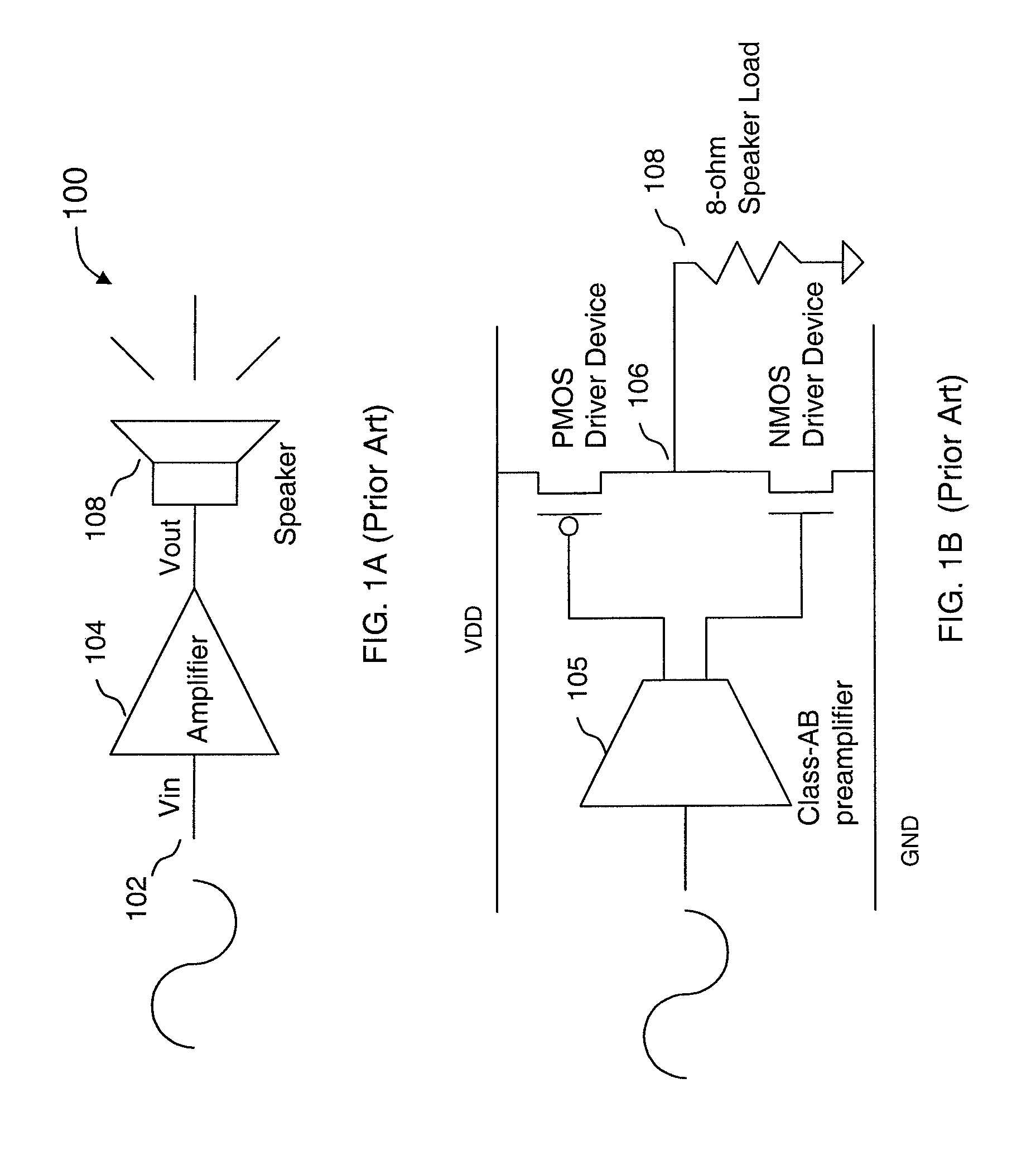
BACKGROUND OF THE INVENTION[0001]The present invention relates generally to CMOS integrated circuit techniques. More specifically, embodiments of the present invention provide methods and circuits for protecting power amplifier output circuit.[0002]Amplifier circuits are ubiquitous in modern electronic devices. An electronic amplifier increases the power and / or amplitude of a signal. In many applications, power amplifier circuits are used at the output stage of a system to drive an external device. Merely as an example, in an audio system, an output power amplifier is often used to drive an external speaker.[0003]Power amplifier circuits output stages can be classified as class A, B, AB, and C for analog signal amplification. This classification is based on the portion of the input signal cycle during which the amplifying device conducts.[0004]A Class A amplifier operates over the whole of the input cycle such that the output signal is a magnified replica of the whole input with no ...

Claims


Application Information

Patent Timeline
Patent Type & Authority Patents(United States)
IPC IPC(8): H03F1/52
CPCH03F1/523H03F3/187H03F3/3022H03F2200/444H03F2200/03
Inventor WONG, LANCE
Owner NUVOTON
Features
  • R&D
  • Intellectual Property
  • Life Sciences
  • Materials
  • Tech Scout
  • Unparalleled Data Quality
  • Higher Quality Content
  • 60% Fewer Hallucinations
Learn More