Implantable therapeutic device control system

a control system and therapeutic device technology, applied in the field of implantable cardiac stimulation devices, can solve the problems of reducing the mechanical pumping reducing the capacity for complete filling, and limiting the sealing capability of the heart, so as to reduce dysynchrony and improve cardiac outpu

Inactive Publication Date: 2010-05-18
PACESETTER INC
View PDF2 Cites 17 Cited by
  • Summary
  • Abstract
  • Description
  • Claims
  • Application Information

AI Technical Summary

Benefits of technology

[0008]At least certain aspects of the invention are based on emerging data that indicates that relatively small changes in interval timing of an implantable therapy device can significantly reduce dysynchrony and improve cardiac output in at least certain patients. Certain aspects of the invention are also responsive to phenomena in at least certain patients of change of their condition over time throughout an implantatio

Problems solved by technology

For example, diseased myocardium reduces the mechanical pumping capabilities of the heart.
Damaged valves can limit the sealing capabilities of the heart reducing capacity for complete filling and/or emptying.
Impaired conduction and/or abnormalities in intrinsic activation can result in inappropriate/impaired stimulation of the cardiac tissue.
Existing CRT devices do not necessarily have algorithms or capacity for adjusting or optimizing interval timing between pacing stimuli in different locations.
While such CRT devices have been shown to benefit a number of CHF patients, there remain a significant proportion of patients who exhibit substantially less beneficial response to existing cardiac resynchronization therapies.
This can result in indications for change in an existing programmed set of interval timing operational parameters of an implantable device.
While systems exist for telemetrically communicating with an implanted device in the impla

Method used


Image

  • Implantable therapeutic device control system
  • Implantable therapeutic device control system
  • Implantable therapeutic device control system

Examples


Embodiment Construction

[0024]Reference will now be made to the drawings wherein like numerals refer to like parts throughout. The following description is of the best mode presently contemplated for practicing the invention. This description is not to be taken in a limiting sense but is made merely for the purpose of describing the general principles of the invention. The scope of the invention should be ascertained with reference to the issued claims. In the description of the invention that follows, like numerals or reference designators will be used to refer to like parts or elements throughout.

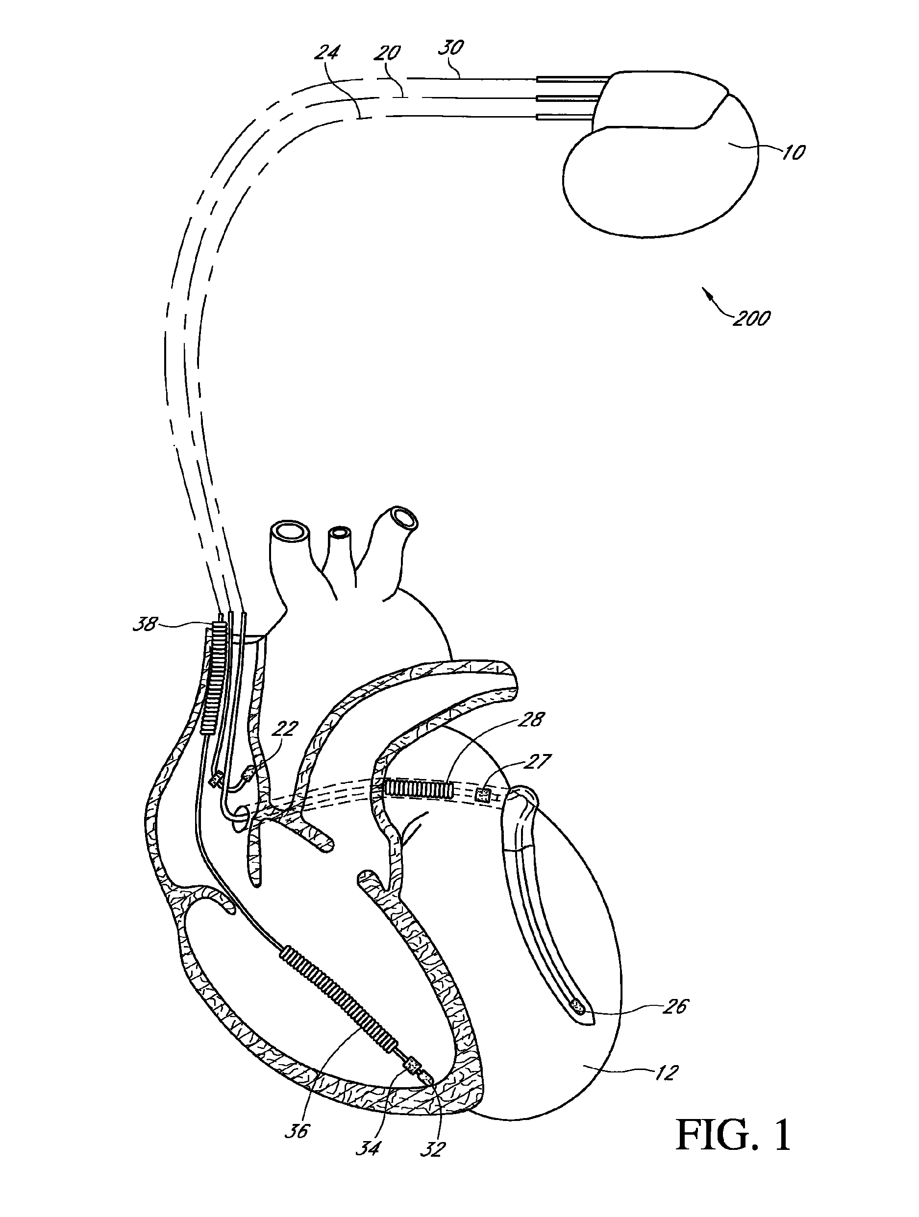
[0025]In one embodiment of a therapy system 200, as shown in FIG. 1, a device 10 comprising an implantable cardiac stimulation device 10 is in electrical communication with a patient's heart 12 by way of three leads, 20, 24 and 30, suitable for delivering multi-chamber stimulation and shock therapy. To sense atrial cardiac signals and to provide right atrial chamber stimulation therapy, the stimulation device 10...


PUM


Abstract

A control system for an implantable cardiac therapy device, the device defining a plurality of sensing vectors including at least one impedance sensing vector and operating under a set of a plurality of variable operating parameters that define conditions for delivery of therapy and wherein the control system evaluates signal quality from the at least one impedance sensing vector and, if the quality is sufficient to discern valvular events, the control system adjusts the set of operating parameters to dynamically improve cardiac performance, including synchrony with valvular events, and if the quality is insufficient to discern valvular events, but sufficient to discern peaks, the control system adjusts the set of operating parameters to dynamically improve cardiac performance independent of valvular events, and if the quality is insufficient to discern peaks, the control system adjusts the set of operating parameters to induce cardiac performance towards a defined performance goal.

Description

BACKGROUND OF THE INVENTION[0001]1. Field of the Invention[0002]The invention relates to the field of implantable cardiac stimulation devices and to improved systems and methods of adjusting implantable devices for individual patients.[0003]2. Description of the Related Art[0004]Numerous patients suffer from disease conditions that affect their cardiac performance. For example, diseased myocardium reduces the mechanical pumping capabilities of the heart. Damaged valves can limit the sealing capabilities of the heart reducing capacity for complete filling and / or emptying. Impaired conduction and / or abnormalities in intrinsic activation can result in inappropriate / impaired stimulation of the cardiac tissue.[0005]Implantable cardiac stimulation devices have been developed to provide therapy for certain patients suffering impaired cardiac function. Implantable cardiac stimulation devices generally include an implantable stimulation pulse generator and a microprocessor based controller r...

Claims


Application Information

Patent Timeline
IPC IPC(8): A61B5/04
CPCA61B5/7221A61N1/368A61N1/3627A61N1/3622A61B5/053
Inventor SCHECTER, STUART O.
Owner PACESETTER INC
Why Eureka
Try Eureka