Multiple power supply apparatus with improved installability

a multi-power supply and installability technology, applied in non-electric variable control, process and machine control, instruments, etc., can solve the problems of increasing the weight and space required for installation of liquid-cooling systems, affecting the installation efficiency of liquid-cooling systems in vehicles, and affecting the installation efficiency of liquid-cooling systems. , to achieve the effect of improving the installability

Active Publication Date: 2010-06-01
DENSO CORP
View PDF20 Cites 33 Cited by
  • Summary
  • Abstract
  • Description
  • Claims
  • Application Information

AI Technical Summary

Benefits of technology

[0033]In view of the background, an object of at least one aspect of the present invention is to provide multiple voltage supply apparatuses installed in a vehicle, each of which has improved installability.

Problems solved by technology

Note that the electrical loads for example include lighting equipment, sound devices, and control units, which are susceptible to decrease in power supply voltage.
Such liquid-cooling systems essentially include issues in which the more the system scale increases with the system structure complicated, the more the weight and a space required for installation of liquid-cooling systems increase.
This makes it difficult to install such a liquid-cooling system in in-vehicle power devices.
However, it is difficult to reduce a heat transfer area of an indirect heat exchange unit required to dissipate heat absorbed by the heat transfer medium into the atmosphere.
In this case, however, the cables may be routed for comparatively long distances in the engine compartment, causing the routing of the cables to be complicated.
The long and complicated routings of the cables may make it difficult to locate some of the cables away from high-temperature devices and / or rotating members located in the engine compartment.
The former may result in malfunction in some of the cables, and the latter may interfere with the rotation of the rotating members.
The long and complicated routings of the cables may make it difficult to prevent some of the cables from being located close to the front (forward end) of the vehicle.
This may cause brakes in some of the cables to be unavoidable in the event of a frontal crash.
This way however may cause substantially identical problems due to the long and complicated routings of the cables by which the first and second batteries and the power transfer unit are connected to each other.
The long and complicated routings of the cables may increase:power loss due to increase in resistance of the cables; andweight of the dual voltage apparatus.
The control units installed in the various vehicles are operative to switch on and off power semiconductor devices that operate at high values of power, which may cause the power semiconductor devices, such as power transistors, to generate heat.
Similarly, because in-vehicle batteries containing electric double layer capacitors repeatedly are frequently charged and discharged depending on variations in power required for in-vehicle electrical loads, they may internally generate a large amount of heat.
This may cause the charging system to increase in size and weight, and cause the charging system structure to be complicated.
In addition, the charging system structure may increase power consumption of the whole of the components (the cooling fan, motor, and motor controller), which may cause the battery to be exhausted.
As described above, installation of the air-cooling system in the charging system may cause the cost and / or the fuel consumption of the vehicle to deteriorate.

Method used


Image

  • Multiple power supply apparatus with improved installability
  • Multiple power supply apparatus with improved installability
  • Multiple power supply apparatus with improved installability

Examples


first embodiment

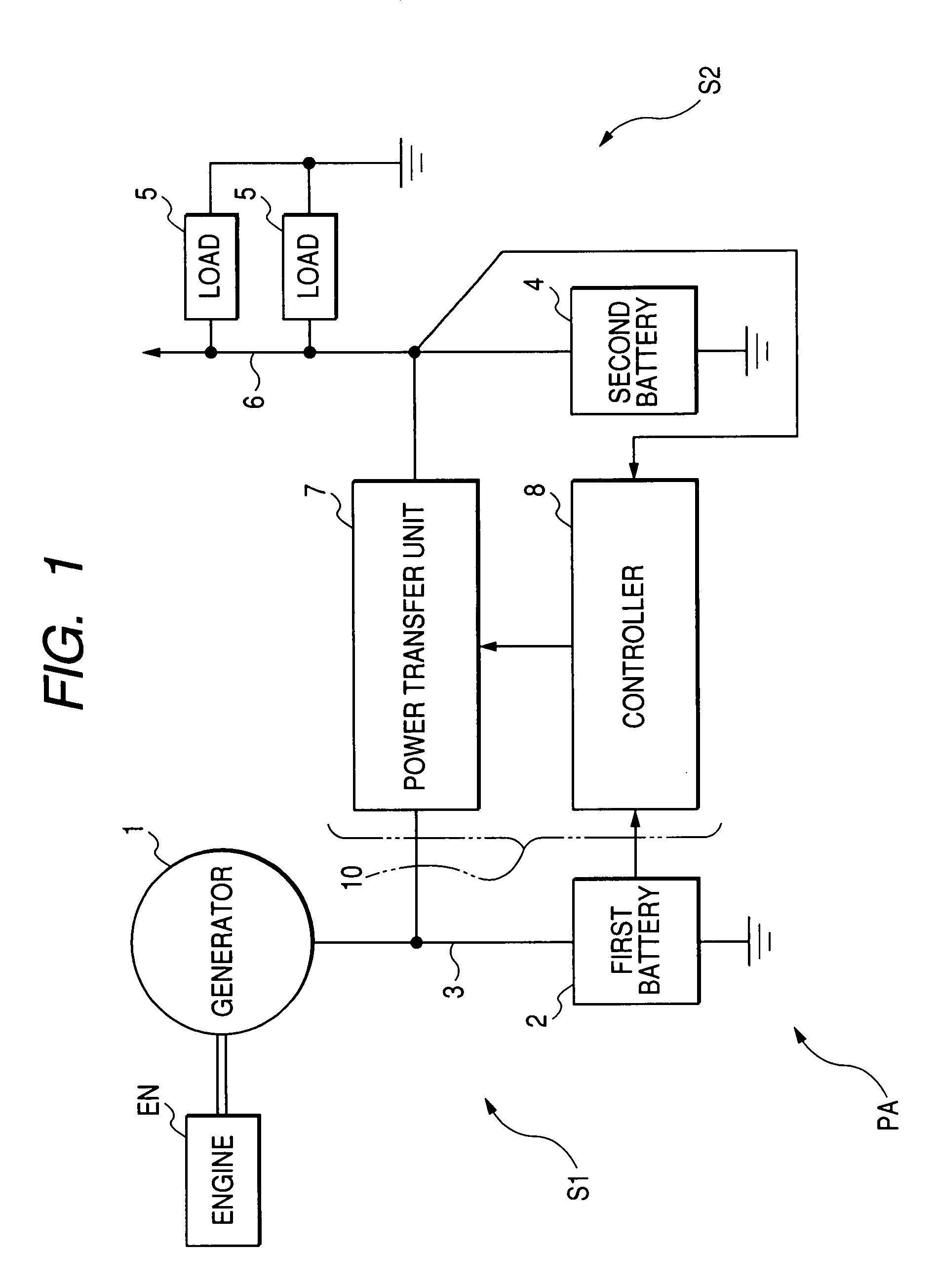
[0065]An example of the circuit structure of a multiple power supply apparatus PA installed in a vehicle according to a first embodiment of the invention is schematically illustrated in FIG. 1.

[0066]Referring to FIG. 1, the multiple power supply apparatus PA includes a generator 1 incorporating a rectifier. The multiple power supply apparatus PA includes a first battery 2 with positive and negative terminals, the positive terminal of which is electrically coupled to the generator 1 via a first power supply line 3, and the negative terminal of which is electrically connected to a ground line.

[0067]The multiple power supply apparatus PA includes a second battery 4 with positive and negative terminals, the positive terminal of which is electrically coupled to a plurality of electrical loads 5 via a second power supply line 6, and the negative terminal of which is electrically connected to the ground line.

[0068]The multiple power supply apparatus PA includes a power transfer unit 7 elec...

third embodiment

[0255]FIG. 15 schematically illustrates an example of the structure of the power-transfer circuit module 10C of a multiple power supply apparatus PA3.

[0256]The circuit configuration of the multiple power supply apparatus PA3 is substantially identical to that of the multiple power supply apparatus PA according to the first embodiment (see FIG. 1).

[0257]Thus, like reference characters are assigned to like parts in the multiple power supply apparatuses according to the first and third embodiments, and therefore, descriptions of the structure of multiple power supply apparatus PA3 are omitted.

[0258]As illustrated in FIG. 15, the power-transfer circuit module 10C includes the metal base plate 71, the double-sided electrode first and second card modules 72 and 73 each integrated with a power MOS transistor, the controller 8, the heatsinks 74 and 75, the resin mold package 76, and the insulating sheet 77. The lead electrodes (control electrodes) of the first and second card modules 72 and...

fourth embodiment

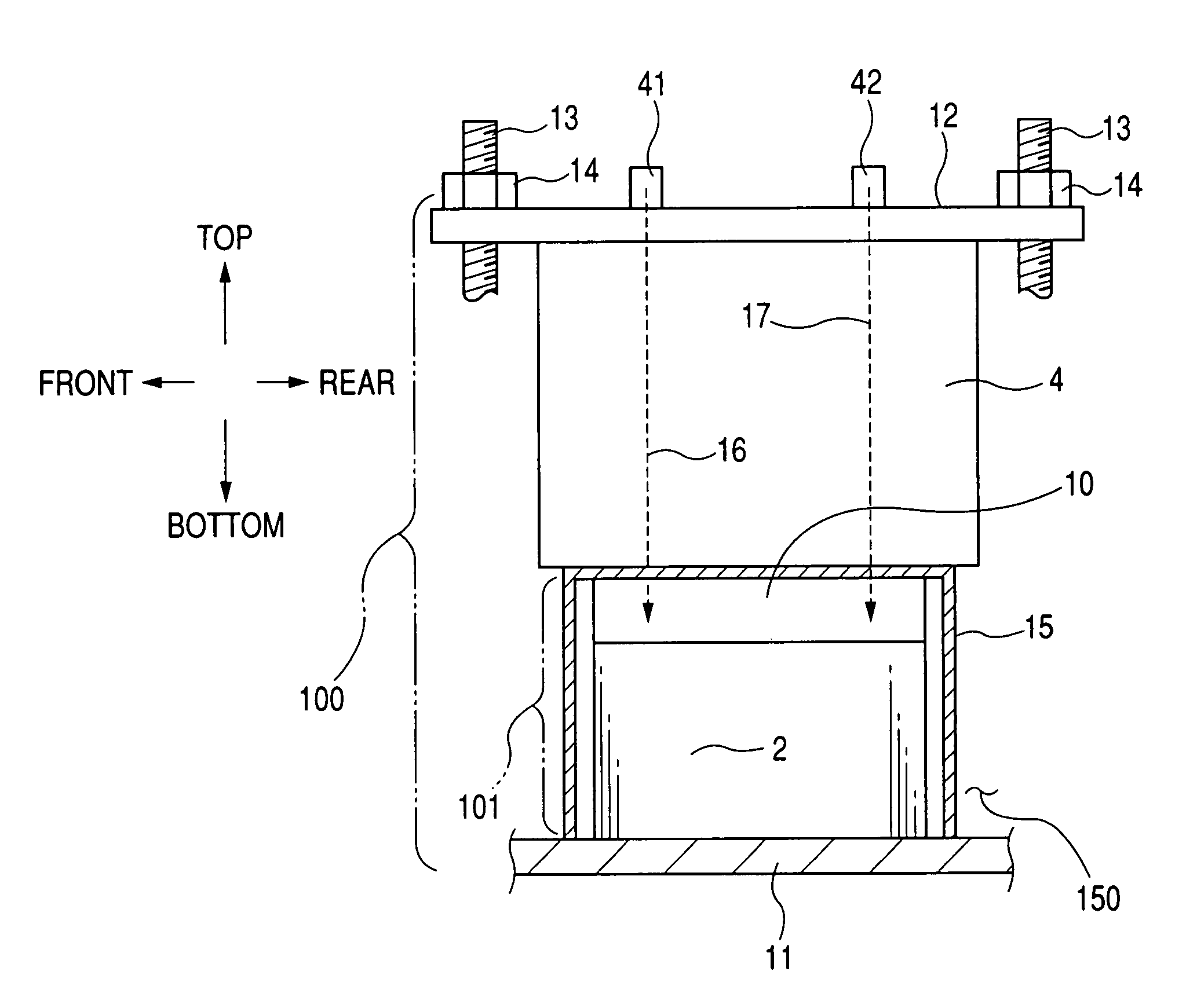
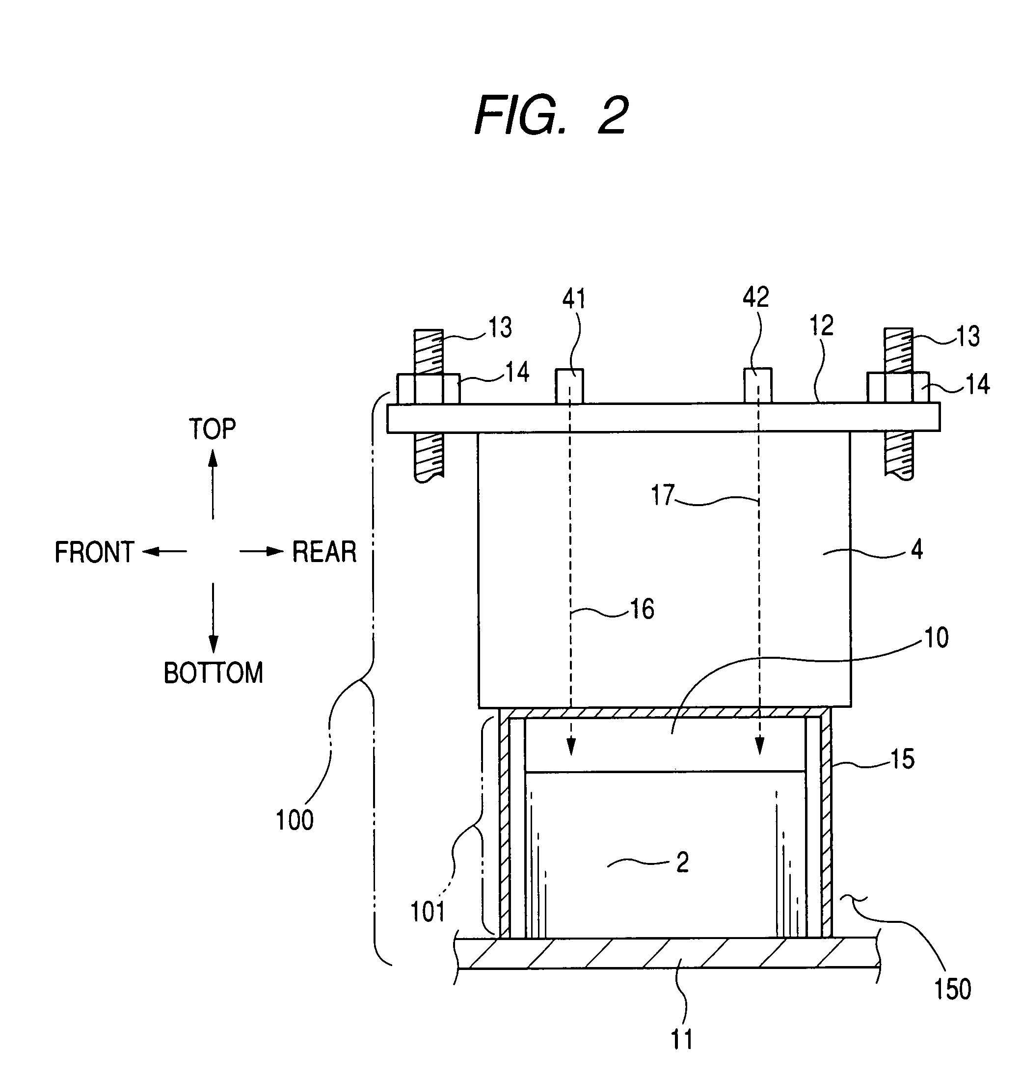
[0298]FIG. 18 schematically illustrates an example of the structure of an air-cooled power system 810 installed in a vehicle according to a fourth embodiment of the present invention.

[0299]As illustrated in FIG. 18, the. air-cooled power system 810 is installed on, for example, the bottom of the vehicle body in the engine compartment 150 in the same manner as the first embodiment.

[0300]The air-cooled power system 810 includes a radiator fan 820 located at the front side of an engine EN installed on the bottom of the vehicle body in the engine compartment 150. The air-cooled power system 810 also includes a motor 830, a radiator 840, a condenser 850, an in-vehicle power device 860, and a suction duct 870.

[0301]For example, the radiator fan 820 has two or more blades BL attached to a shaft of the motor 830, and the shaft of the motor 830 is arranged in parallel to the longitudinal direction of the vehicle. When the motor 830 is energized to rotate the shaft, the blades BL of the radia...


PUM


Abstract

In a multiple power supply apparatus installed in a vehicle, a first power supply system includes a generator and a first battery. The generator is driven by an operation of the engine. The first battery is chargeable by an electrical output of the generator. A second power supply system includes a second battery. The second battery works to supply electrical power to an electrical load installed in the vehicle. A power transfer module is operative to transfer electrical power supplied from the first power supply system based on at least one of the electrical output of the generator and a charged level of the first battery to the second power supply system. The power transfer module is integrally joined to the first battery to constitute a battery module.

Description

CROSS REFERENCE TO RELATED APPLICATIONS[0001]This application is based on Japanese Patent Applications 2006-077598, 2006-077606, 2006-077613, and 2006-077618 filed on Mar. 20, 2006, respectively. This application claims the benefit of priority from these applications, so that the descriptions of which are all incorporated herein by reference.FIELD OF THE INVENTION[0002]The present invention relates to multiple power supply apparatuses having improved installability. The present invention also relates to air-cooled power systems with a simplified structure.BACKGROUND OF THE INVENTION[0003]Recently, power supply apparatuses with two different voltage batteries have been installed in hybrid vehicles and engine vehicles. The power supply systems with two different voltage batteries will be referred to as “dual voltage apparatuses” hereinafter.[0004]A dual voltage apparatus is normally equipped with a first power supply system including an engine-driven generator and a higher battery. Th...

Claims


Application Information

Patent Timeline
Patent Type & Authority Patents(United States)
IPC IPC(8): H02J7/14G05D17/00H02J1/10
CPCH01M10/482H01M10/5004H01M10/5016H01M10/5032H01M10/5051H01M10/5067H01M10/5073H02J7/1423H01M10/5046Y02T10/7005H01M10/625H01M10/6553H01M10/6563H01M10/647H01M10/6551H01M10/6566H01M10/613Y02T10/70Y02E60/10H02J7/342
Inventor TANAKA, KATSUNORIKATO, AKIRATANIBATA, MICHINORIKUROYANAGI, YUTAKA
Owner DENSO CORP
Why Eureka
Try Eureka