Storage apparatus for controlling power saving modes of multiple disk devices of different specifications
a technology of storage apparatus and power saving mode, which is applied in the field of data management and storage apparatus, can solve the problems of consuming affecting the original processing performance of the controller for i/o access requests, and provoking cost increases for the overall storage apparatus, so as to increase the capacity of the storage apparatus, increase the size of the memory, and consume a large amount of controller memory resources
- Summary
- Abstract
- Description
- Claims
- Application Information
AI Technical Summary
Benefits of technology
Problems solved by technology
Method used
Image
Examples
first embodiment
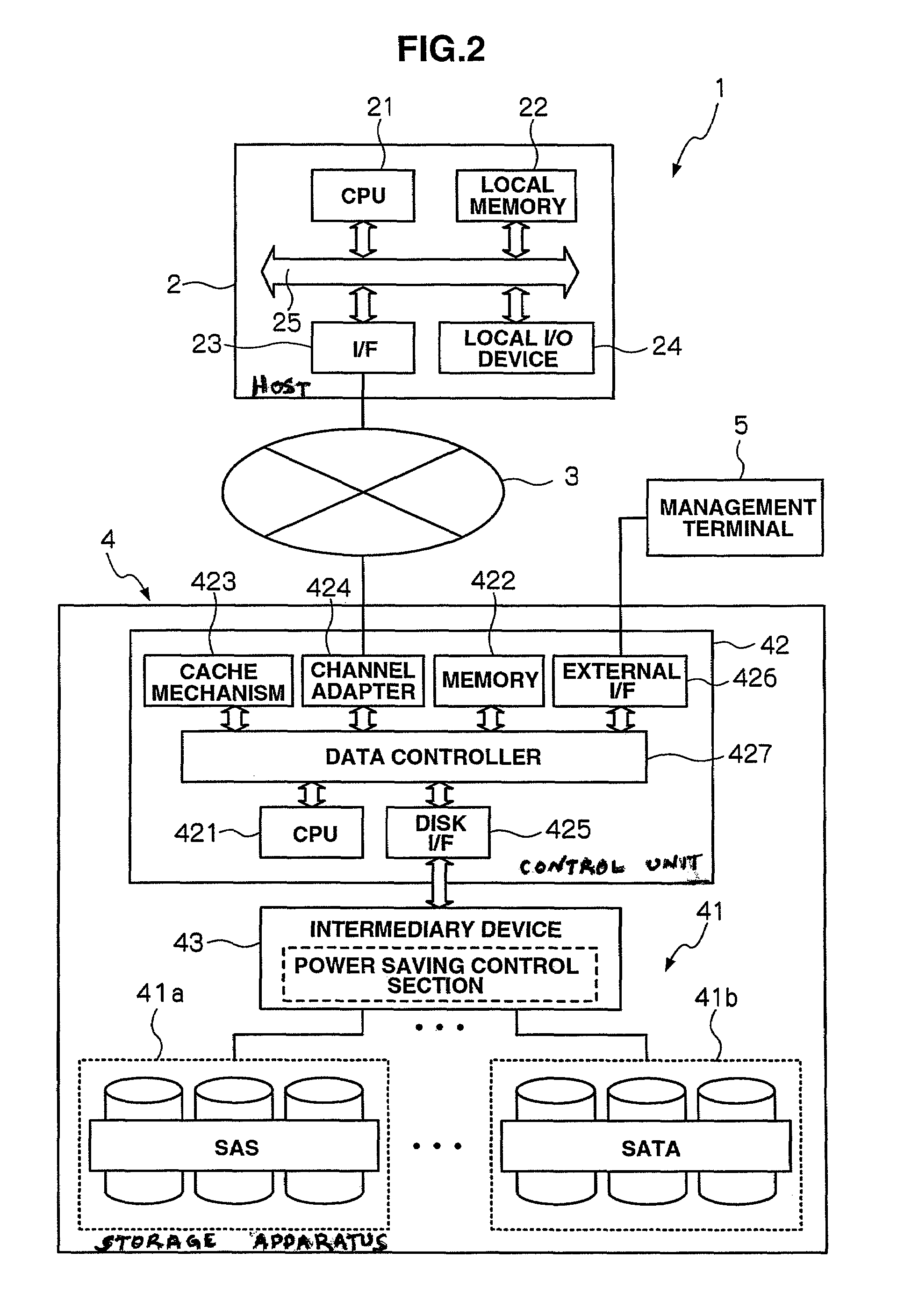
[0058]FIG. 2 shows a configuration for a storage system of an embodiment of the present invention. Referring to FIG. 2, a storage system 1 includes a storage apparatus 4 operatively connected to a host apparatus 2 via a network system 3. The storage system 1 further includes a management terminal 5 operatively connected to the storage apparatus 4.
[0059]The host apparatus 2 typically corresponds to a personal computer, workstation, or mainframe, etc. The host apparatus 2 has hardware resources, such as a CPU 21, a local memory 22, an interface 23, and a local input / output device 24, that are operatively connected together by an internal bus 25. The host apparatus 2 includes software resources, such as a device driver, an operating system (OS), and one or more application programs.
[0060]The host apparatus 2 executes various programs under the control of CPU 21, and achieves desired processing in cooperation with hardware resources. Typically, the host apparatus 2 executes the applicat...
modified example 1
[0116]A mechanism (corresponding to (2) above) for protecting delayed write data using the non-volatile buffer memory 436a of the intermediary device 43 is described below in details.
[0117]FIG. 14 is a flowchart illustrating the operation of the intermediary device 43 of an embodiment of the present invention. It is noted that a description is given where the disk device 41 connected to the port 434 constituting the target is a SAS disk device.
[0118]As with the embodiment described above, when a write request command from the host apparatus 2 is sent to the storage apparatus 4, the controller unit 42 temporarily stores write target data correlating to the command to the cache memory as a result of the action of the cache mechanism 423, and also sends the command (containing the write target data) to the intermediary device 43 in order to write the write target data to the disk device. 41.
[0119]Referring to FIG. 14, when the write request command is received from the controller unit ...
modified example 2
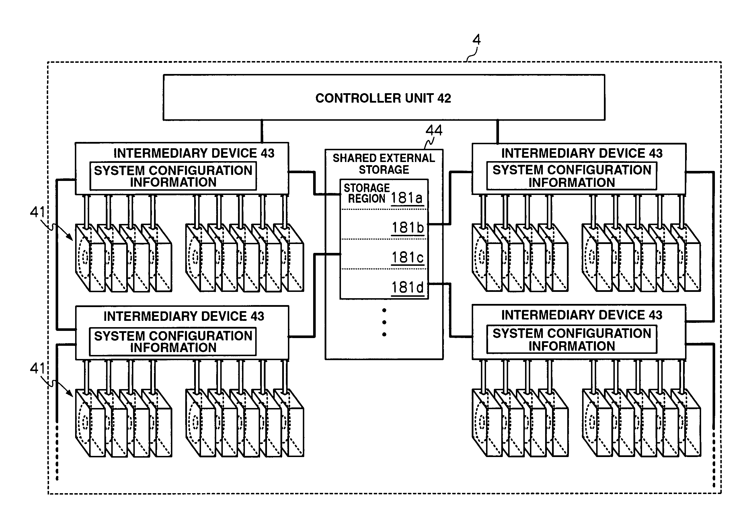
[0125]The following is a mechanism (corresponding to (3) described above) for protecting delayed write data using external storage connected to the intermediary device 43. Memory of a comparatively large capacity is required in order to protect delayed write data. Thus, the modified example as discussed below is configured in such a manner as to cache in external storage connected to the intermediary device 43. It is noted that an external storage may be, for example, a specific area formed on a disk device 41 operatively connected to the intermediary device 43, or may be a storage device capable of being externally fitted to the intermediary device 43. The storage device capable of being externally fitted may be, for example, a storage device provided as an independent unit connected using a cable, etc., or a card type memory device installed using a slot. A non-volatile memory is preferable in the event that the storage medium is a memory.
[0126]FIG. 15 is a flowchart illustrating ...
PUM
 Abstract
Description
Claims
Application Information
 - R&D
- Intellectual Property
- Life Sciences
- Materials
- Tech Scout
- Unparalleled Data Quality
- Higher Quality Content
- 60% Fewer Hallucinations
Browse by: Latest US Patents, China's latest patents, Technical Efficacy Thesaurus, Application Domain, Technology Topic, Popular Technical Reports.
© 2025 PatSnap. All rights reserved.Legal|Privacy policy|Modern Slavery Act Transparency Statement|Sitemap|About US| Contact US: help@patsnap.com


