Soil conditioning device

a technology of soil conditioning and soil, which is applied in the direction of non-skid devices, thinning machines, spades, etc., can solve the problems of reducing oxygen, limiting aeration activity, and reducing the efficiency of processes and associated devices, so as to improve soil permeability, reduce water runoff, and improve the effect of soil permeability

Inactive Publication Date: 2010-06-08
TERRACON TECH LLC
View PDF61 Cites 23 Cited by
  • Summary
  • Abstract
  • Description
  • Claims
  • Application Information

AI Technical Summary

Benefits of technology

[0014]The present invention is comprised of a soil conditioning device having a series of prow shaped peripheral ridge members optionally joined by sub-ridge members circumscribing a disc, wheel or drum. When the soil conditioning device is rolled across the soil surface, a series of consolidated prow shaped hollows and optional weir formations are created in the soil enhancing soil permeability and reducing water runoff. The primary purpose of the soil conditioning device is enabling the soil to retain rain water where it falls and consequently reduce erosion and increase aeration, water retention and infiltration of the soil and provide for multitasking capabilities.
[0016]The soil conditioning device is comprised of a relatively lightweight material. Such materials may include wood, polyurethane foam, rubber, silicon rubber, synthetic rubber, Hytrel™, urethane, various plastics or polymeric materials, and combinations thereof. Preferably, the soil conditioning device is manufactured from plastic or polymeric materials such as high density polyethylene (HDPE), polyvinyl chloride, vinyl, or other such moldable plastic materials. HDPE has been found to be advantageous since it is a material which is light weight, strong, flexible and exhibits self cleaning capabilities when applied to the soil. Linear Low Density Polyethylene (LLDP) has also been found to be advantageous since it is a low cost polymer having highly flexible qualities and possessing great durability. Optionally, the use of UV-stabilizers such as carbon black may be added to improve its weather resistance. Combinations of various polymeric materials have also exhibited the desired properties of being relatively lightweight and a having a degree of flexibility. Further unique polymers such as Teflon type polymers may be added that provide a high resistance to soil sticking to the surface of the wheel. In addition to other types of light weight material list in this section such as wood, rubber, etc, materials such as stainless steel, iron, or newer classes of ceramics may be formed into the leading and trailing prow shaped sections of the wheel to assist in the clod breaking activities of the wheel. Additionally, these materials used in the top ⅛th to ¼th inch of the top edge of the ridge member improve the wear and life of the tool.
[0017]The soil conditioning device is molded producing a circular outer skin having a series of prow shaped peripheral ridge members optionally joined by sub-ridge members surrounding a hollow core. This design and material of manufacture allows the shape, hardness, and weight to be adjusted at its point of use by a farmer or other user for various soil types. This adjustability enables it to work efficiently in a variety of conditions. The adjustment is accomplished by filling the hollow core through a valve in the soil conditioning device. The core may be filled with compressed air or other gases, water or other liquids, gels, solids, expanding foam, a mixture of air and water, or any combination thereof to obtain the desired shape, hardness, and / or weight.
[0018]The soil conditioning device molds or consolidates the soil upon which it is rolled by applying light pressure to the soil surface in a substantially horizontal direction so as to lightly consolidate or bind the outermost surface of the soil together. Consolidating the soil surface lightly sticks the outermost surface soil particles together leaving a porous permeable soil surface for greater infiltration capabilities. As the device travels through the soil, the soil flows over and around the various component surfaces of the device restructuring the soil to a desired form. While the soil flows over and around the various surfaces, the soil is caused to lift and flow in a bow wave fashion behind the device or tool having a plurality of devices. While the soil is in the flowing state, the device is rotating within the soil flow and forming, ushering, and gently kneading the soil while ushering it into place producing a series of consolidated hollows and optional weirs, therefore leaving the soil surface in a “Geometric Ordered Roughness (GOR), necessary for the control of erosion caused by water and wind, in a process known as “Hydroforming”. This process of consolidating the soil requires little or no additional pressure or force perpendicular to the soil surface thus providing little or no compaction to the surface soil. The consolidation is accomplished in a substantially lateral direction and shapes a structure in the soil consisting of various curves and angles forming prow shaped hollows and optional adjoining weirs which increases the soil surface area. The increase in permeability and surface area of the soil surface both contribute to the increase in soil infiltration and consequent reduction in erosion. Additionally, the prow shape of the ridge allows for the device to be operated at speeds necessary for efficient farm practices.
[0019]The soil conditioning device of the present invention consolidates the soil surface into a series of permeability or porous prow shaped hollows and optional adjoining weirs controlling water flow and increasing the surface area of the soil contacting rain water thus increasing the effective infiltration rate of the soil. These prow shaped hollows and optional adjoining weirs are designed to slow and / or stop flowing water while allowing it to infiltrate the soil. These structures are consolidated evenly over their entire surface of the soil increasing the surface area of the soil and increasing the infiltration rate of the soil. Additionally, increase surface area increases soil warming from the sun allowing for improved seed germination. Below this molded or consolidated surface, the soil structure remains loose thus allowing water to percolate throughout the soil. These prow shaped hollows and optional adjoining weirs increased porosity, infiltration rate, and water absorbing capability of the soil directly reducing erosion of the soil by substantially eliminating and / or slowing water runoff. Additionally, surface ponding on fields is reduced since rainfall or irrigation water is more easily absorbed by the soil having a higher porosity and surface area in contact with the water. Further, aeration of the soil is also increased.
[0020]The soil conditioning device has many applications and benefits. It is capable of working on most all soil types and agricultural applications, such as planting, surface water control, soil warming, reducing wind erosion, cultivating and plowing, or common construction applications, such as scraping, building berms, reclaiming land, or even creating meridians between interstate highways.

Problems solved by technology

During this farming process, soil is often left in a loose condition where the soil is subject to moisture evaporation and erosion.
However, these traditional processes and associated devices fall short of providing a system or device which reduces erosion, reduces water runoff, increases water infiltration, allows multitasking and fail to leave the surface soil in a better prepared seedbed.
As a result of the compaction, the soil surface is sealed which causes the soil surface to become substantially impervious to water infiltration and limits aeration activity reducing oxygen.
When weight is applied to the soil, the soil structure is compressed and soil particles are commonly arranged by the compression into unfavorable growing condition formats or consistency.
The greater the weight or load to the soil, the greater the amount of compaction or unfavorable segregation.
This practice does little to provide a system which reduces water runoff, increase water infiltration, or allow multitasking.
Even though these more recently designed machines are lighter than the Dixon Wheel™ and other similar devices, they are all still relatively heavy and still produce many of the problems previously described such as decreased water infiltration capabilities of the soil and decreased aeration.
However, when water is applied to the loose soil it impacts and dislodges the fine particles of soil and organic matter on the sides of the dikes and washes them into the bottom of the pools.
These particles of soil then seal the bottom of the pools which reduces the infiltration capability of the soil and diminishes the reduction of runoff Additionally, the loose soil is eroded from the field in both light and heavy rainfall events.
The fine particles eroded have fertilizer and pesticides attached to them which then moves offsite and is undesirable.
However, there are several disadvantages associated with no-till.
No-till requires the use of herbicides to eliminate competition from weeds which raises production costs.
Crop residue left on the soil hinders soil warming and drying, making planting more difficult and reduces seed germination.
Conventional tillage systems cannot be used to incorporate fertilizers and herbicides.
The heavy residue or foliage left on the land may result in poor seed soil contact thus reducing seed germination.
This pitching of the soil fills in the created pools with fine particles that seal the bottom of the pools which further reduces the infiltration capability of the soil.
Furthermore, pitching of the soil destroys a portion of the structure of the pool leading to early failure of the remaining pool structure.

Method used


Image

  • Soil conditioning device
  • Soil conditioning device
  • Soil conditioning device

Examples


Embodiment Construction

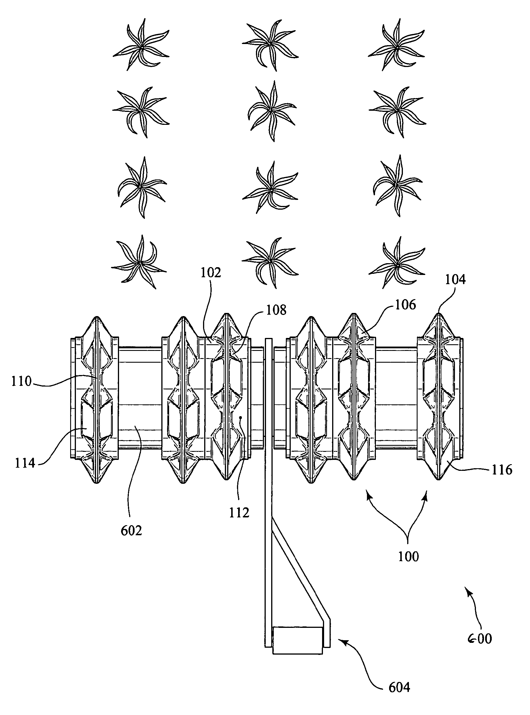
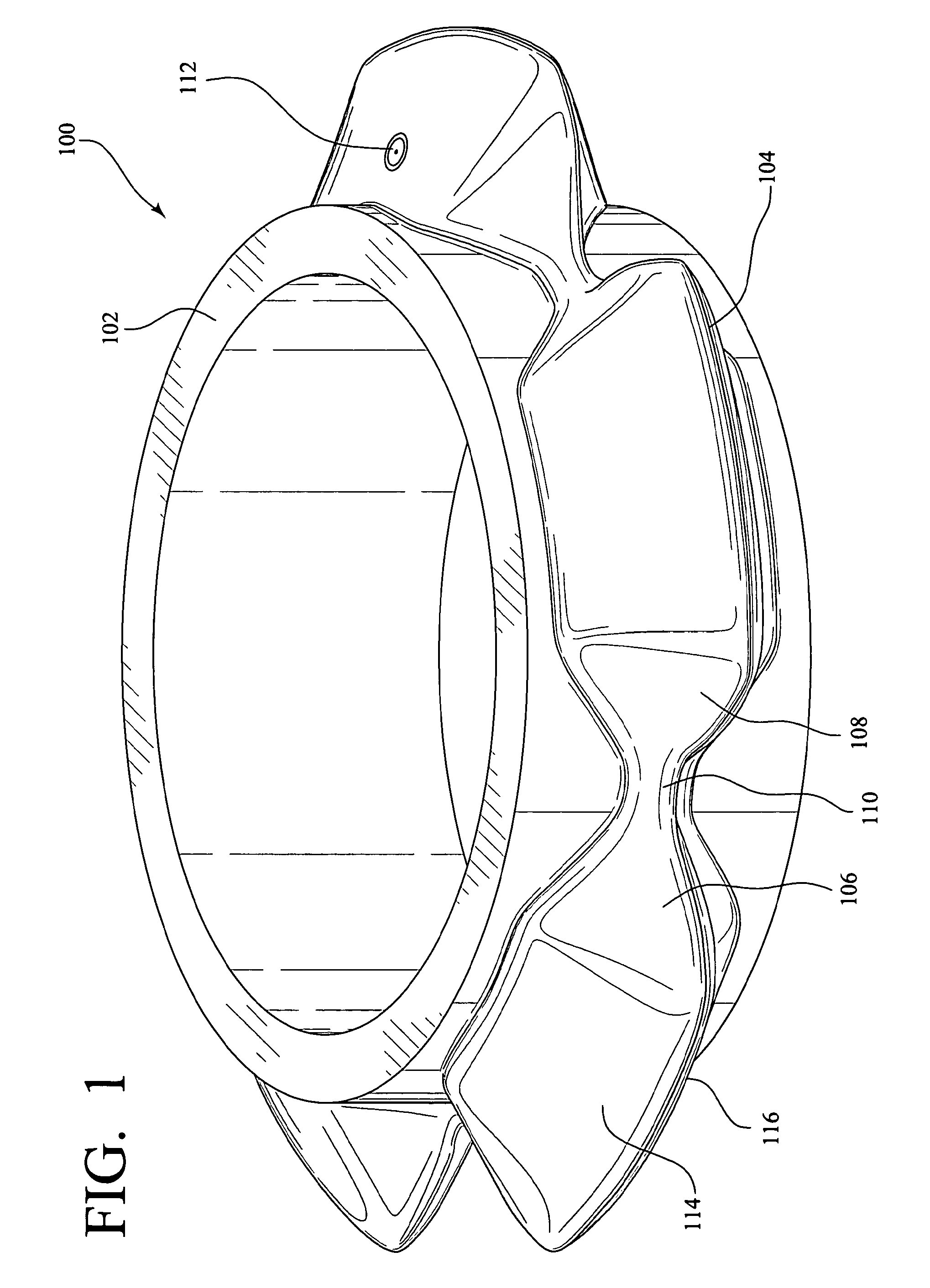
[0042]FIG. 1 shows soil conditioning device 100 having a series of prow shaped peripheral ridge members 104 joined by sub-ridge members 110 circumscribing wheel or disc 102. Each of the plurality of ridge members 104 has a leading prow shaped surface 106 and a trailing prow shaped surface 108. Spanning between each leading surface 106 and trailing surface 108 is a subridge member 110. This embodiment of the soil conditioning device may also be described as a wheel member 102 having a central continuous outer peripheral ridge of varying heights about wheel member's 102 circumference. The peripheral ridge is formed by prow shaped peripheral ridge members 104 having leading prow shaped surface 106 and trailing prow shaped surface 108. Ridge members 104 are joined or interposed by sub-ridge members 110 and have a rounded top surface and side walls 114 and 116 sloping toward wheel member 102.

[0043]Soil conditioning device 100 is shown circumscribing wheel 102 and being of a unitary mater...


PUM


Abstract

A soil conditioning device having a series of peripheral ridge members having a leading and trailing prow shaped surface circumscribing a disc, wheel or drum. Optionally the prow shaped peripheral ridge members are joined by sub-ridge members forming a single ridge of varying heights circumscribing the disc, wheel or drum. The invention is also of a method for creating a permeable soil surface using the apparatus herein.

Description

CROSS-REFERENCE TO RELATED APPLICATIONS[0001]This continuation-in-part application claims priority to and benefit from U.S. patent application Ser. No. 11 / 176,569, filed on Jul. 7, 2005, now U.S. Pat. No. 7,478,684, issued on Jan. 20, 2009.BACKGROUND OF THE INVENTION[0002]1. Field of the Invention[0003]This invention relates to soil conservation, more specifically toward an apparatus for conditioning surface soils thereby increasing infiltration and aeration.[0004]2. Description of the Related Art[0005]Traditional farming comprises tasks such as plowing, disking, harrowing, seeding, fertilizing, and harvesting. During this farming process, soil is often left in a loose condition where the soil is subject to moisture evaporation and erosion. There is an increased demand to accomplish these farming tasks in a manner to conserve the soil by reducing erosion and to conserve the water by increasing the infiltration capability of the soil. Additionally, there is a demand to multitask thes...

Claims


Application Information

Patent Timeline
Patent Type & Authority Patents(United States)
IPC IPC(8): A01B39/08
CPCA01B29/04A01B29/041Y10T152/10171
Inventor WARD, KEITHCARR, CHARLES STEPHEN
Owner TERRACON TECH LLC
Why Eureka
Try Eureka