Method and device for reducing axial thrust and radial oscillations and rotary machines using same
a technology of axial thrust and radial oscillation, which is applied in the direction of liquid fuel engines, vessel construction, marine propulsion, etc., can solve the problems of general failure of the machine, excessive axial load is especially harmful to the axial thrust bearing, and the reliability of the rotary machine operation
- Summary
- Abstract
- Description
- Claims
- Application Information
AI Technical Summary
Benefits of technology
Problems solved by technology
Method used
Image
Examples
first embodiment
Design Features of the Invention as Shown on FIG. 1
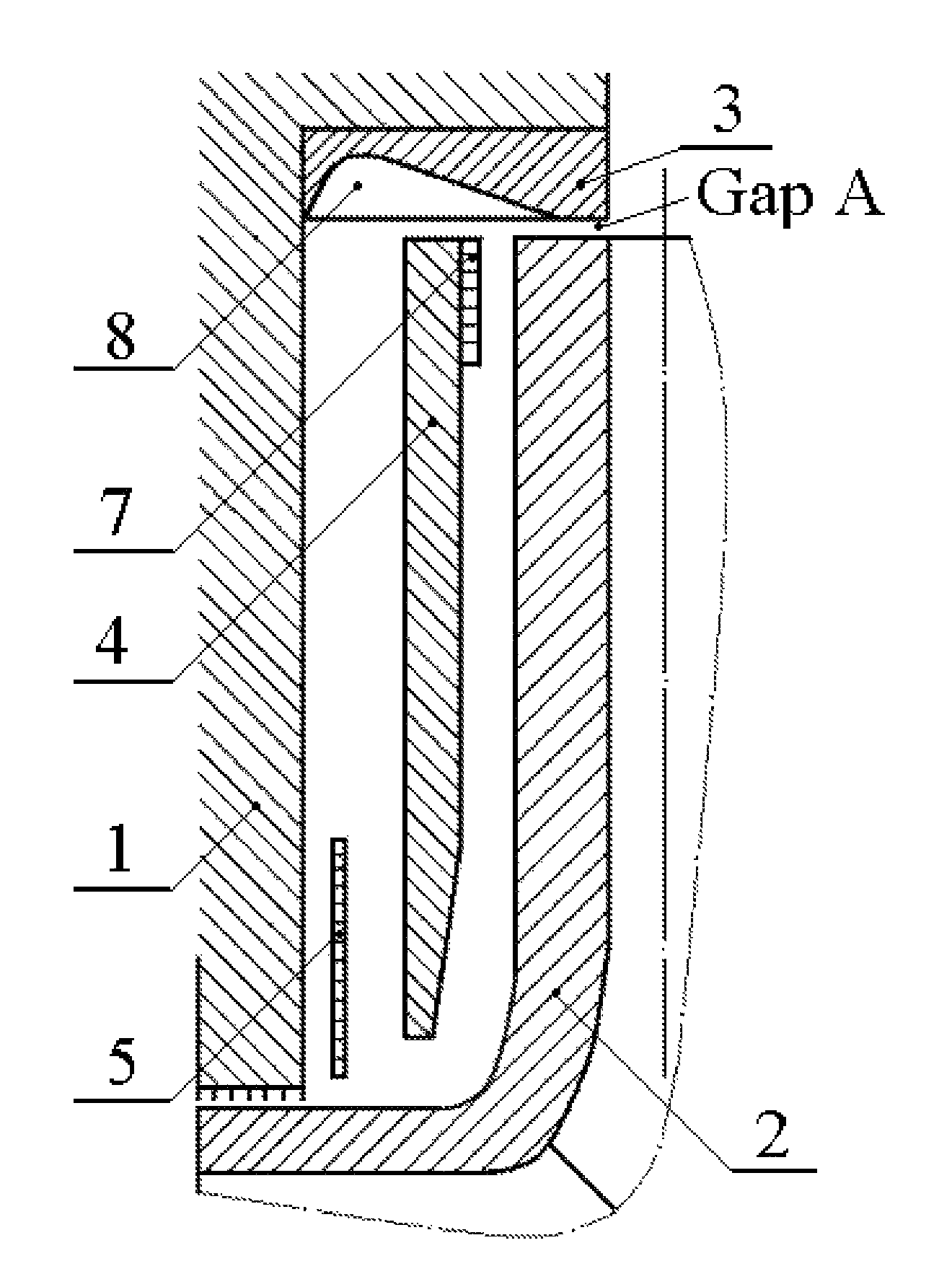
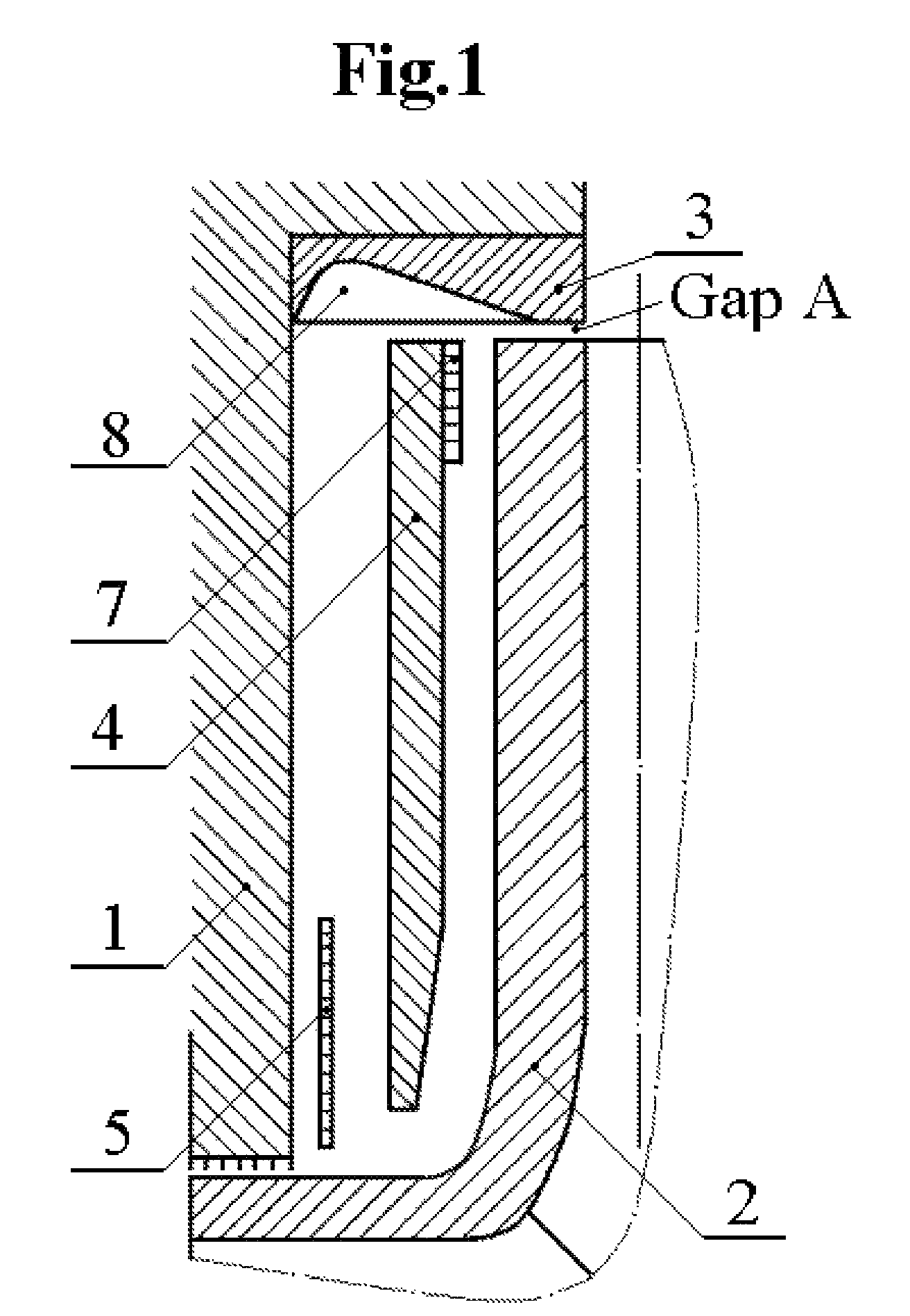
[0052]In FIG. 1, rotating rotor (2) induces outward rotating flow of the adjacent fluid, which then enters the peripheral vane system (8). Such flow, combined with leakage flow through the annular gap at the periphery of rotor (2) (Gap A), having tangential momentum, is redirected by peripheral vanes (8) into radially inward flow directed toward hub between the stator (1) and subdividing means (4). Stator (1) is assumed to be a part of the housing shroud of the rotary machine. Radial ribs (not shown) may be used to attach subdividing means (4) and additional optional radial disc (5) to stator (1) and to further condition flow. The purpose for the optional radial disc (5) is to assist in improving flow conditions (preferably, reverse direction to shaft using anti-rotation vanes, not shown) for leakage flow entering shaft seal.
[0053]An important feature shown in FIG. 1 is that subdividing means (4) is designed to separate the flow in ...
second embodiment
Design Features of the Invention as Shown on FIG. 2
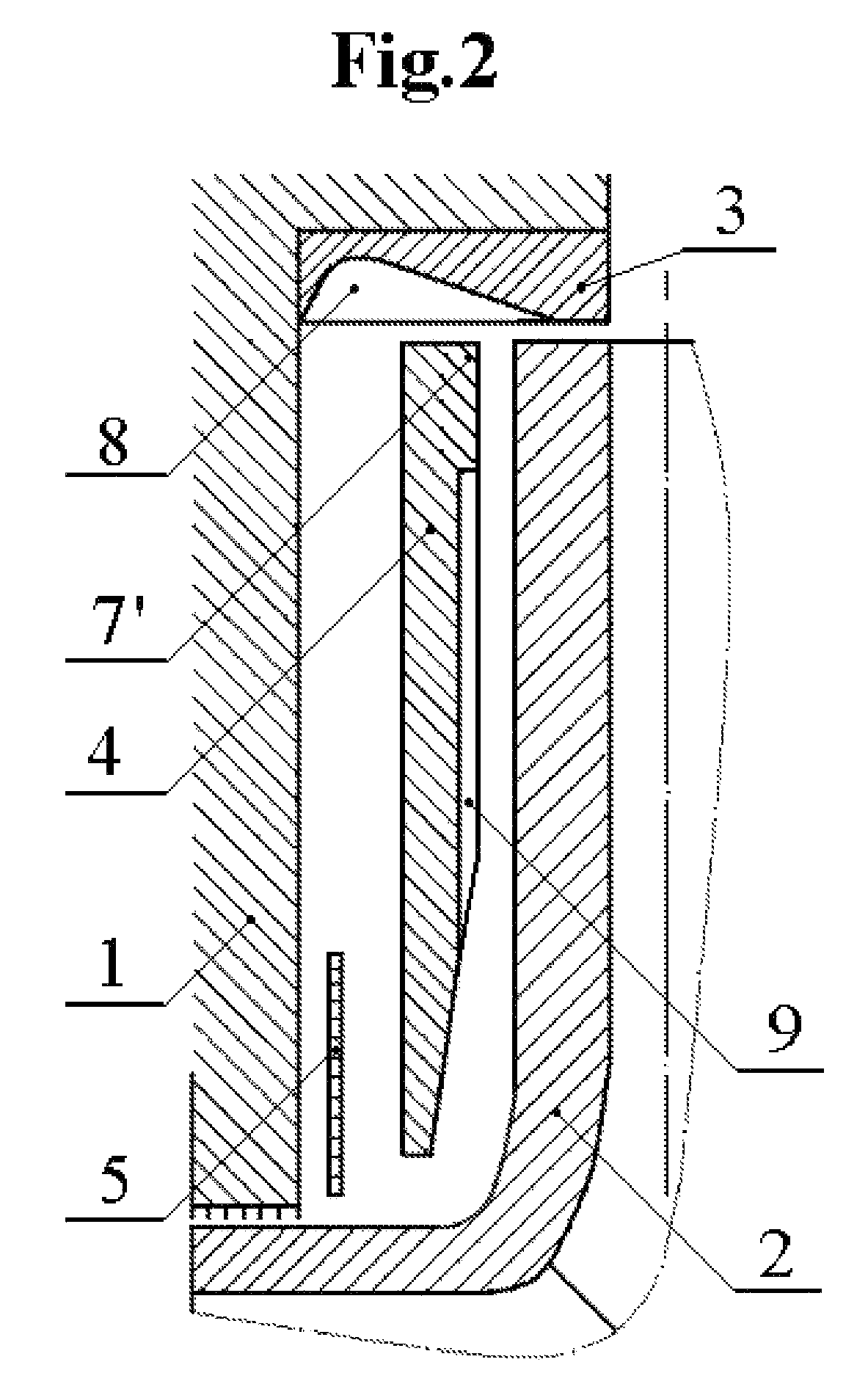
[0060]Many design elements of FIG. 1 are incorporated into FIG. 2. The primary difference is that raised ring-shaped restrictive means (shown as position 7 in FIG. 1) has been removed, and that spiral grooves (9) (or vanes, wavy surface, Rayleigh steps, etc.) have been cut into the subdividing means (4) on the side facing the rotating rotor. Such spiral grooves (as shown) do not extend all the way to the outer perimeter of the subdividing means (4) therefore forming an outer ring face section (7′) (the landing area) that functions as a peripheral restrictive means (such as the dam of hydrodynamic ring seals), where the high pressure produced by the spiral grooves results in lift at the leading edge of restrictive means (7′), providing separation forces between the two opposing faces. Compared to the design in FIG. 1, the design features of FIG. 2 allow for increasing / improving axial stiffness and damping characteristics. The periphe...
third embodiment
Design Features of the Invention as Shown on FIG. 3
[0061]Many design elements of FIG. 2 are incorporated into FIG. 3. The primary difference in FIG. 3 is that radial ribs such as spiral grooves (9′) and restrictive means (7″) are placed on the face of rotating rotor (2), not on stationary subdividing means (4). Such placement on the peripheral restrictive means on the rotating rotor is especially beneficial when the working fluid has low viscosity (such as gases or cryogenic liquids), and when additional performance is desired (increased thrust or increased fluid stiffness).
PUM
 Abstract
Description
Claims
Application Information
 - R&D
- Intellectual Property
- Life Sciences
- Materials
- Tech Scout
- Unparalleled Data Quality
- Higher Quality Content
- 60% Fewer Hallucinations
Browse by: Latest US Patents, China's latest patents, Technical Efficacy Thesaurus, Application Domain, Technology Topic, Popular Technical Reports.
© 2025 PatSnap. All rights reserved.Legal|Privacy policy|Modern Slavery Act Transparency Statement|Sitemap|About US| Contact US: help@patsnap.com


