All-fiber laser coupler with high stability

a technology of all-fiber lasers and couplers, applied in the field of all-fiber laser couplers with high stability, can solve the problems of increasing the complexity of the system disclosed by brosnan, the cost and difficulty of the apparatus described by abrams et al., and the relatively low power output of a single fiber laser without amplification or other power increasing techniques

Inactive Publication Date: 2010-06-15
HRL LAB
View PDF37 Cites 10 Cited by
  • Summary
  • Abstract
  • Description
  • Claims
  • Application Information

AI Technical Summary

Problems solved by technology

Hence, the apparatus described by Abrams et al. may be expensive and difficult to implement.
However, the power output of a single fiber laser without amplification or other power increasing techniques is relatively low.
However, the additional circuitry required to detect and compensate for the relative optical phase shifts increases the complexity of the system disclosed by Brosnan.
Also, fiber amplifiers are generally less efficient than fiber oscillators (lasers).
Hence, the system disclosed by Brosnan would be considered more complex and less efficient than a system based on a plurality of fiber oscillators.
However, this configuration does not provide for phase-locking between the light propagating in each of the cores.
A key problem with multiple-core fiber oscillator systems, such as the system disclosed by Scifres, is heat dissipation.
Hence, the power of the multiple-core fiber oscillator systems will be limited by the ability to dissipate the heat generated by the active regions away from the multiple-core fiber, similar to the way that glass rod lasers are limited in average power scaling.
Furthermore, as the optical power in each fiber is increased, this prior art has the disadvantage that the combined power must propagate in the core of the single central fiber.
When the combined optical power is high, undesirable nonlinear effects in, or damage to, the single central fiber may occur.
Further, the acoustic waves may also be amplified by this effect, generating an acoustic intensity that can easily damag

Method used


Image

  • All-fiber laser coupler with high stability
  • All-fiber laser coupler with high stability
  • All-fiber laser coupler with high stability

Examples


Embodiment Construction

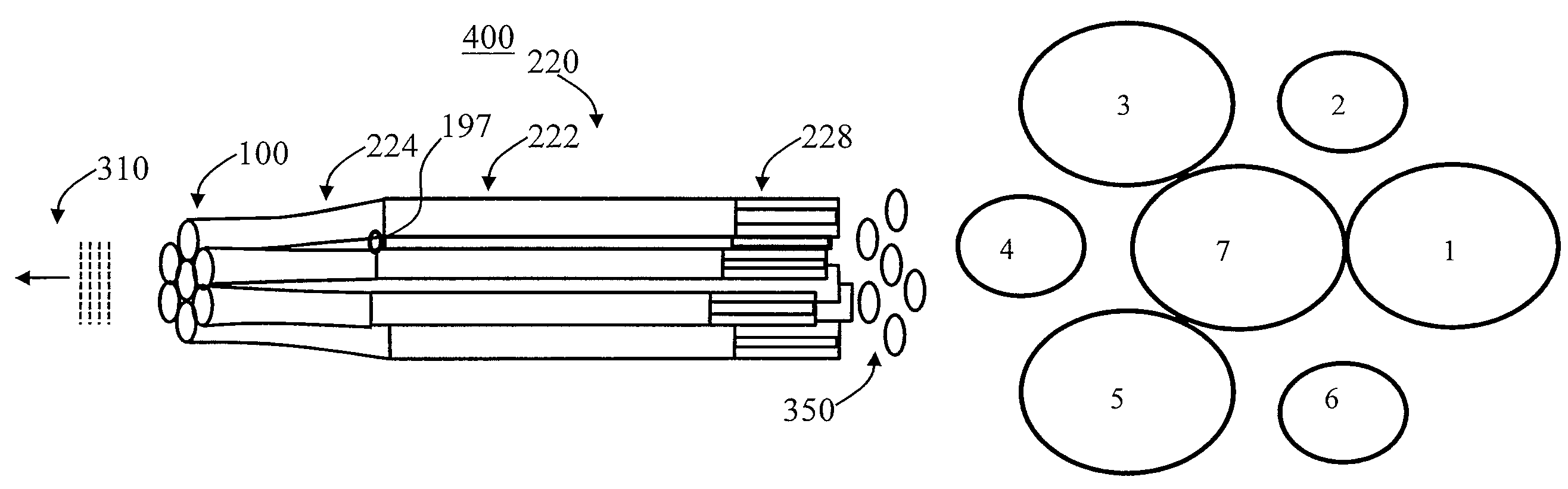
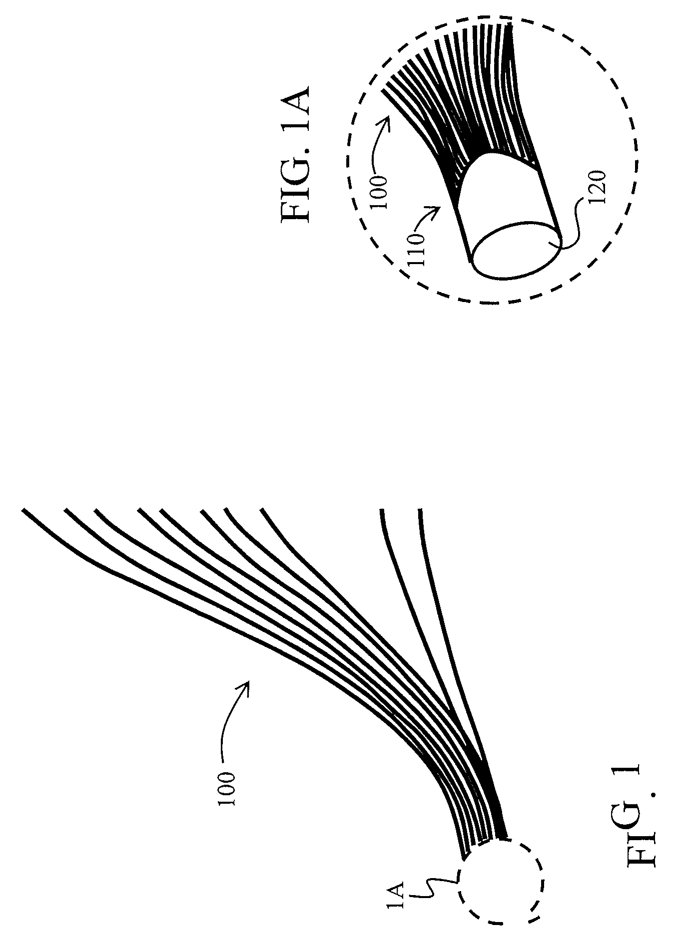
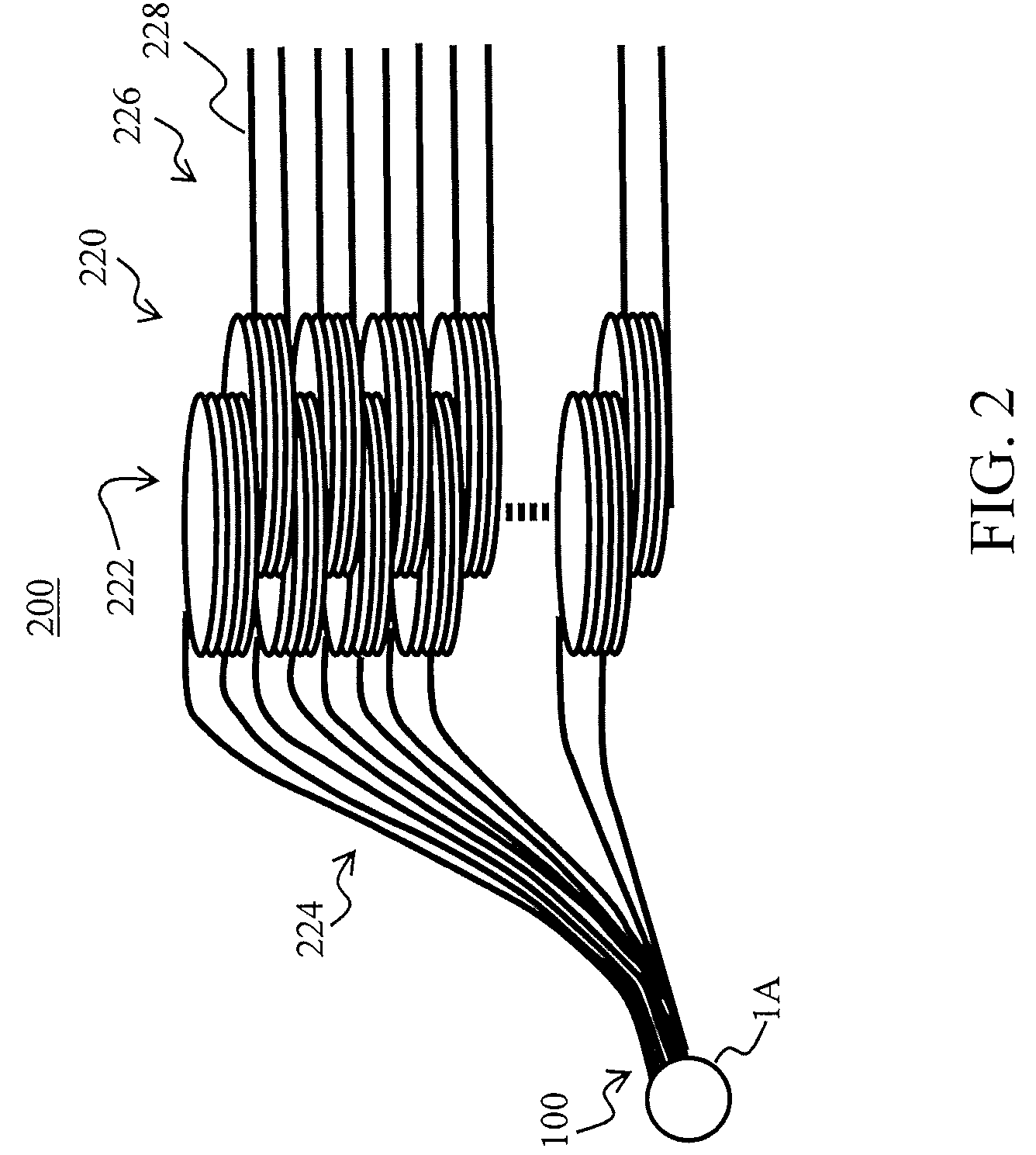
[0050]Embodiments of the present invention provide a method and apparatus for coupling a plurality of laser devices and utilizing interactions between the plurality of laser devices to form a flat wavefront coherent optical output that is stable against perturbations. Embodiments of the present invention also employ one or more interferometrically dark fibers to ensure that the outputs from interferometrically lit fibers have fairly uniform intensity.

[0051]FIGS. 1-7D provide methods and apparatuses for generating a high power laser output with a flat wavefront coherent output. FIGS. 8-12D provide methods and apparatuses for a flat wavefront coherent output from a laser oscillator array that is stable against perturbations.

[0052]As described herein, an interferometrically dark fiber is a member of a fiber array, which, under uniform illumination, transmits no light because of destructive interference between the light coupled directly into that fiber from the external illumination an...


PUM


Abstract

An optical coupler is provided for a passive coherent combination of fiber lasers/amplifiers. A plurality of optical fibers are arranged in a close-packed hexagonal array having 1+3n(n+1) fibers with (3/2)(n2−n)+3 interferometrically dark fibers and (3/2)(n2+3n)−2 light fibers, where n is an integer greater than or equal to 1. Each optical fiber has a first end and a second end. The plurality of optical fibers are fused together along a section of each optical fiber proximate the first end of each optical fiber to form a fused section having a fiber axis. The fused section of the plurality of optical fibers is tapered to form a tapered region. A facet is at an end of the fused section. The facet is disposed in a direction perpendicular to the fiber axis. The coherent pattern is highly stable against perturbation.

Description

CROSS-REFERENCE TO RELATED APPLICATION(S)[0001]The subject matter of the present application is related to U.S. patent application Ser. No. 10 / 893,106, now U.S. Pat. No. 7,274,717, entitled “Dark Fiber Laser Array Coupler,” which is incorporated herein by reference. The subject matter of the present application is also related to U.S. patent application Ser. No. 10 / 759,510, entitled “Method and Apparatus for Coherently Combining Multiple Laser Oscillators” and to U.S. patent application Ser. No. 10 / 759,511, entitled “Method and Apparatus for Combining Laser Light,” both of which are incorporated herein by reference.BACKGROUND OF THE INVENTION[0002]1. Field of the Invention[0003]This disclosure relates generally to lasers, and more particularly, to obtaining a flat wavefront coherent output from a laser oscillator array that is stable against perturbations.[0004]2. Description of Related Art[0005]As described herein, the term “optical” is given the meaning used by those skilled in th...

Claims


Application Information

Patent Timeline
IPC IPC(8): G02B6/26G02B6/04
CPCG02B6/04G02B19/0061G02B19/0057G02B19/0028G02B6/425G02B6/262
Inventor MINDEN, MONICA L.WANG, SHUOQIN
Owner HRL LAB
Why Eureka
Try Eureka