
High current density cathode for electrorefining in molten electrolyte

a cathode and high current density technology, applied in the field of electrorefining in molten salt electrolytes, can solve the problems of limiting the efficiency and throughput of the electrorefining process, uranium deposits not continuously falling off the cathode, etc., and achieves the effect of eliminating scraping and electrochemical stripping steps, reducing the cost of scraping

Inactive Publication Date: 2010-06-29
BATTELLE ENERGY ALLIANCE LLC
View PDF6 Cites 5 Cited by
  • Summary
  • Abstract
  • Description
  • Claims
  • Application Information

AI Technical Summary

Benefits of technology

The invention is about a new type of cathode for electrorefining in a molten electrolyte. This cathode has a high current density, meaning it can handle a lot of electricity. This makes it more efficient than conventional cathodes, which means it can process spent nuclear fuel more quickly and effectively. The cathode has a stainless steel tube with a coating of insulating material, which has multiple small holes to expose parts of the tube. This design allows for continuous removal of dendrites, which are the main by-product of the refining process. The invention also includes an electrorefiner apparatus that uses this new cathode and a process for continuously recovering uranium from spent fuel. Overall, this invention improves the efficiency and productivity of electrorefining.

Problems solved by technology

Controlling the morphology of uranium metal, which is the major constituent of spent nuclear fuel, deposited at the cathode has been a challenge for the electrorefining process.
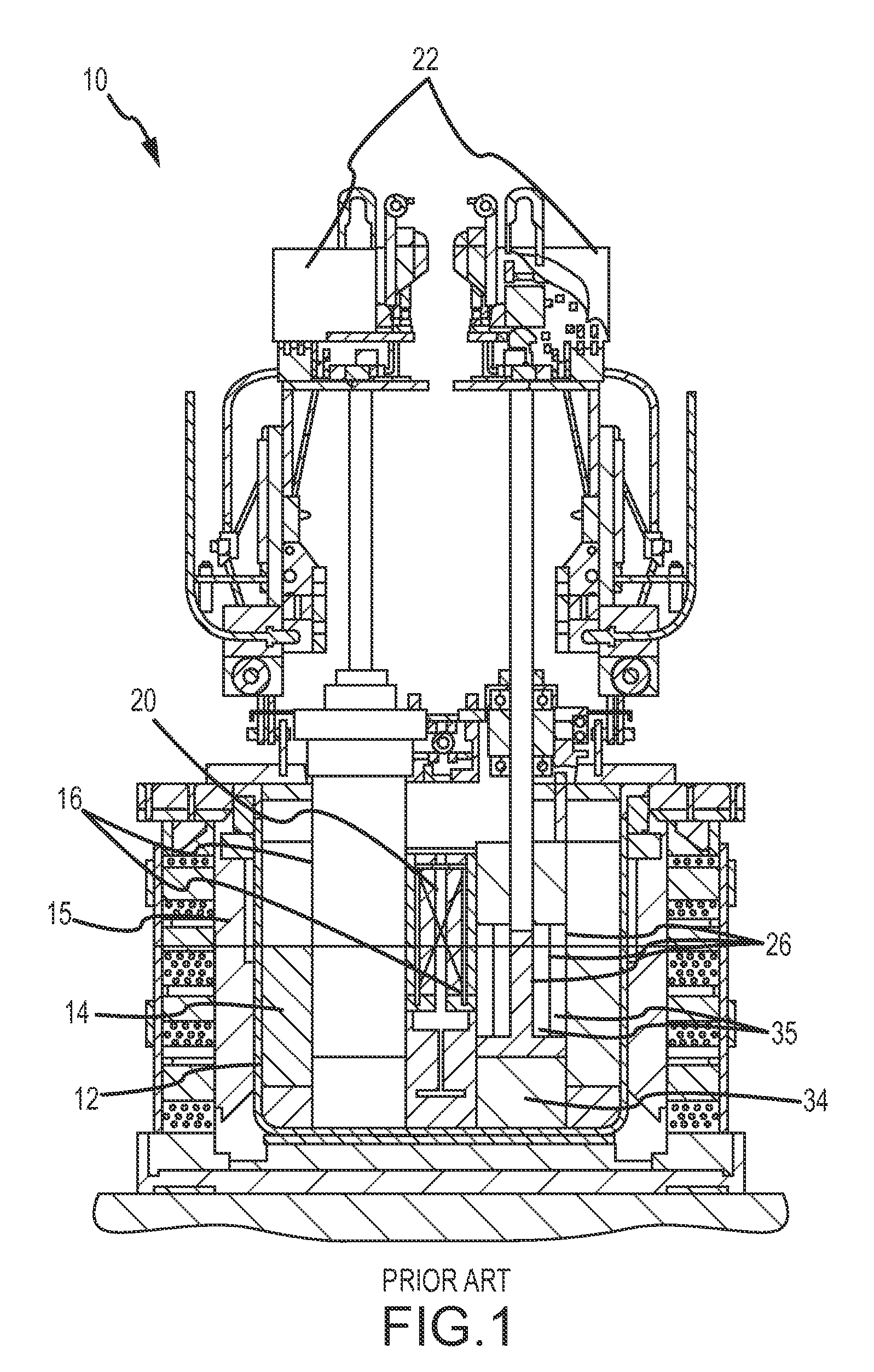
A disadvantage of the Mk-V electrorefiner concentric anode-cathode design is that the uranium deposit does not continuously fall off the cathode as desired.
The stripping and wash steps described above, and the use of scrapers to remove the deposited uranium from the cathode for collection in the product collection bucket, limit the efficiency and throughput of the electrorefining process.

Method used


Image

  • High current density cathode for electrorefining in molten electrolyte
  • High current density cathode for electrorefining in molten electrolyte
  • High current density cathode for electrorefining in molten electrolyte

Examples


Embodiment Construction

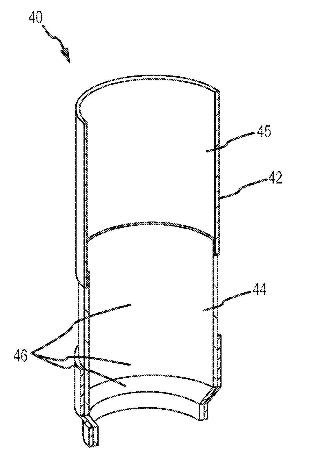
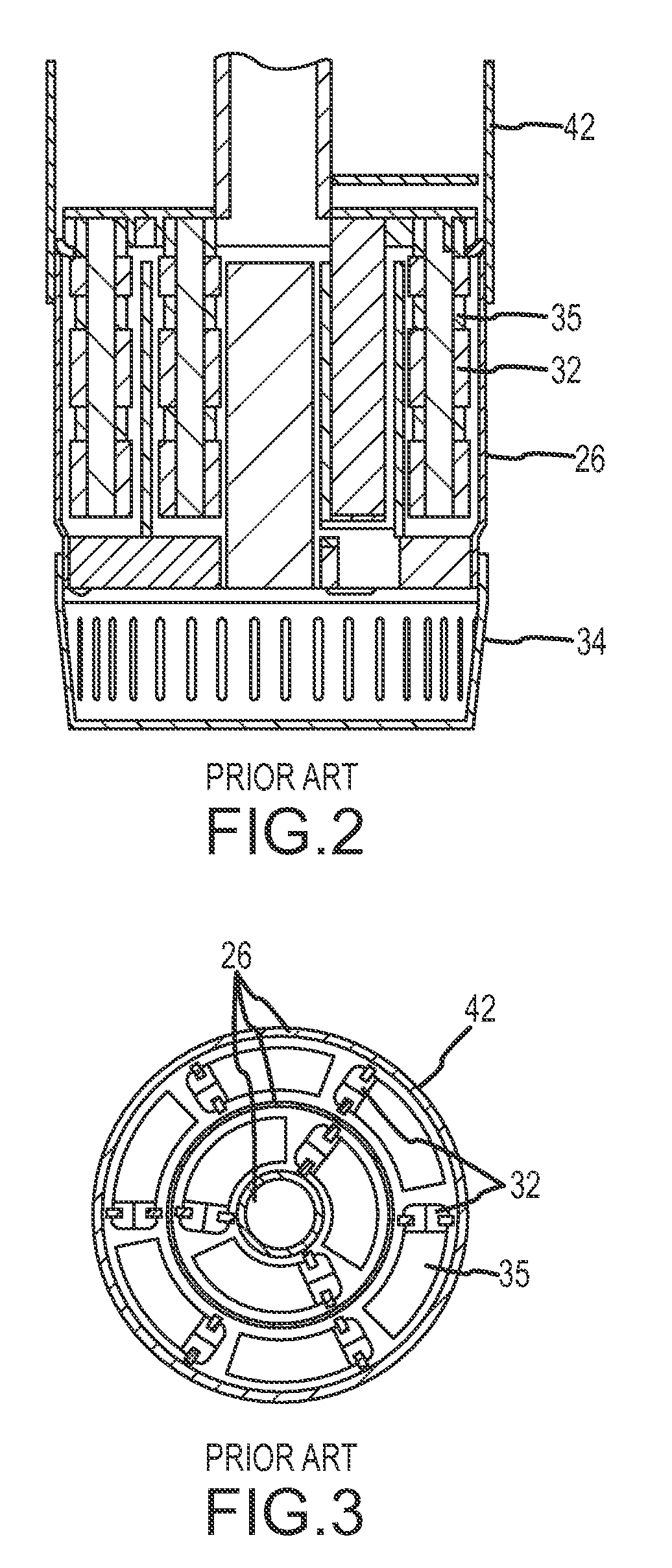
[0016]Referring now to FIG. 4, the cathode tube 40 of the present invention is shown. The present invention eliminates all interior concentric cathode tubes 26 that are shown in FIG. 2 and FIG. 3. Cathode tube 40 comprises an exterior stainless steel tube 42. The interior of cathode tube 40 has an electrical insulating coating 44 attached to a lower portion of the cathode tube 40. In one embodiment of the invention, electrical insulation 44 is comprised of Y2O3 (7%) stabilized ZrO2. The insulating material coating 44 can be plasma sprayed onto the cathode tube 40 interior surface 45 or applied by other known methods. Preferably the insulating coating 44 is at least 0.1 mm in thickness to provide sufficient electrical insulation of the cathode tube 40.

[0017]The electrical insulation coating 44 is perforated to expose portions of the stainless steel cathode tube 42 thereby providing electrical communication between the cathode tube 42 and anode 35. Perforation of the electrical insula...


PUM

PropertyMeasurementUnit
current densityaaaaaaaaaa
cathode current densityaaaaaaaaaa
operating temperatureaaaaaaaaaa

Abstract

A high current density cathode for electrorefining in a molten electrolyte for the continuous production and collection of loose dendritic or powdery deposits. The high current density cathode eliminates the requirement for mechanical scraping and electrochemical stripping of the deposits from the cathode in an anode / cathode module. The high current density cathode comprises a perforated electrical insulated material coating such that the current density is up to 3 A / cm2.

Description

GOVERNMENT RIGHTS[0001]The United States Government has certain rights in this invention pursuant to Contract No. DE-AC07-05-ID14517, between the United States Department of Energy and Battelle Energy Alliance, LLCFIELD OF THE INVENTION[0002]This invention relates to electrorefining in molten salt electrolytes and more specifically to electrorefining utilizing a cathode having a high current density to produce loose dendritic or powdery deposits.BACKGROUND[0003]Electrorefining processes have been used to recover high purity metal or metals from impure feed material and more particularly to recover uranium and plutonium from spent nuclear fuel in a molten salt electrolyte. In the electrorefining process spent nuclear fuel forms the anode. The uranium in the spent fuel is separated from fission products and collected at the cathode through the electrorefining process. Controlling the morphology of uranium metal, which is the major constituent of spent nuclear fuel, deposited at the ca...

Claims


Application Information

Patent Timeline
Patent Type & Authority Patents(United States)
IPC IPC(8): C25B11/03C25C3/34C25C1/22
CPCC25C7/02
Inventor LI, SHELLY X.
Owner BATTELLE ENERGY ALLIANCE LLC
Learn More