Semiconductor light-emitting device

a technology of semiconductors and light-emitting devices, which is applied in the direction of semiconductor devices, lasers, semiconductor lasers, etc., can solve the problems of deterioration of differential efficiency and temperature characteristics, increase of threshold current, and material smallness in lattice constants, etc., to achieve small threshold current, good characteristics, and high differential efficiency

Active Publication Date: 2010-06-29
MITSUBISHI ELECTRIC CORP
View PDF19 Cites 8 Cited by
  • Summary
  • Abstract
  • Description
  • Claims
  • Application Information

AI Technical Summary

Benefits of technology

[0016]It is an object of the present invention to provide a semiconductor light-emitting device which exhibits small threshold current, high differential efficiency and good characteristics, by reducing electrons that overflow an electron barrier that is provided for trapping the electrons in an active layer.
[0020]According to the present invention, the band gap of the final barrier layer is made smaller than the band gap of the barrier layers. Accordingly, an electron barrier formed between the barrier layers and the p-type clad layer is larger than a case where the barrier layers are used as a final barrier layer. As a result, electrons overflowing the electron barrier from the active layer can be reduced.
[0021]Besides, since the final barrier layer is formed on a well layer, it is free from deterioration in crystallinity.
[0025]According to the present invention, the band gap of the first layer is smaller than the bandgap of the plurality of barrier layers. As a result, as compared with the electron barrier formed between the barrier layers and the p-type clad layer, the electron barrier between the first layer and the p-type clad layer can be larger; therefore, electrons overflowing the electron barrier from the active layer can be reduced.

Problems solved by technology

Accordingly, electrons are likely to overflow from the well layer beyond the barrier layer, which often leads to problems such as increase in threshold current, and deterioration of differential efficiency and temperature characteristic.
However, as a barrier layer, when InGaN having the smallest In composition ratio is used or when GaN or AlGaN is used, these materials become smaller in lattice constant as they become wider in band gap, and are exposed to greater tensile distortion.
However, the present inventor has confirmed by simulation that a new problem arises when a barrier layer is made of a material having larger band gap, electrons are likely to overflow beyond the electron blocking layer from a final barrier layer which is closest to the p-side.
Further, in the case of barrier layers of InGaN of smaller band gap than GaN or AlGaN, the rate of electrons overflowing the electron barrier from the final barrier layer is not zero, which may lead to deterioration of threshold current of a semiconductor light-emitting device, differential efficiency, and temperature characteristics.
However, the film forming temperature of an electron blocking layer is higher than that of a well layer by about 200° C. Therefore, if it is attempted to form an electron blocking layer directly on the well layer, after forming the well layer, the film forming temperature must be raised without protecting the surface of the well layer.
In this process, crystallinity of the well layer surface deteriorates.
When a semiconductor light-emitting device is manufactured by using such a well layer deteriorated in crystallinity, electrons trapped in the well layer do not contribute to laser oscillation, and threshold current or differential efficiency may be worsened.

Method used


Image

  • Semiconductor light-emitting device
  • Semiconductor light-emitting device
  • Semiconductor light-emitting device

Examples


first embodiment

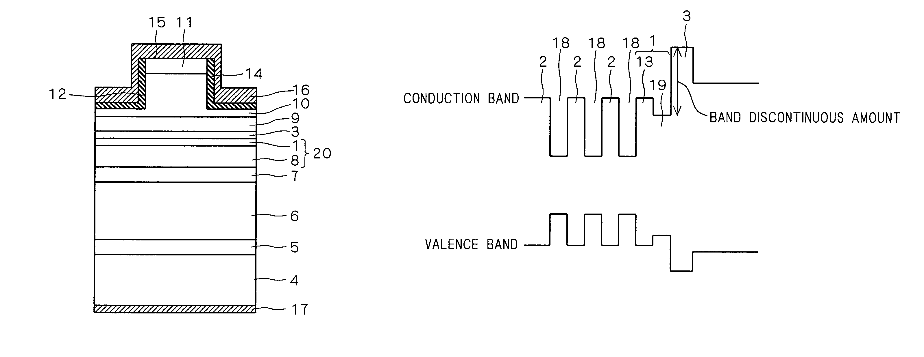
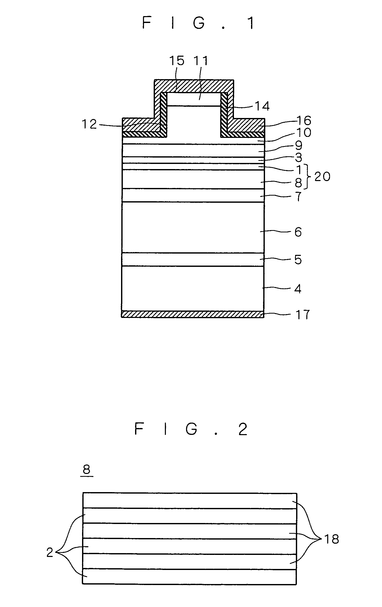
[0035]FIG. 1 is a sectional view showing a configuration of a nitride-based semiconductor laser (semiconductor light-emitting device) according to a first embodiment. This nitride-based semiconductor laser has a ridge structure and an SCH structure.

[0036]As shown in FIG. 1, the nitride-based semiconductor laser according to this embodiment has an n-type GaN buffer layer 5 formed on a Ga surface which is a main surface of a GaN substrate 4. This layer is formed for the purpose of reducing surface undulations on the GaN substrate 4 and laminating the upper layers flatly as much as possible.

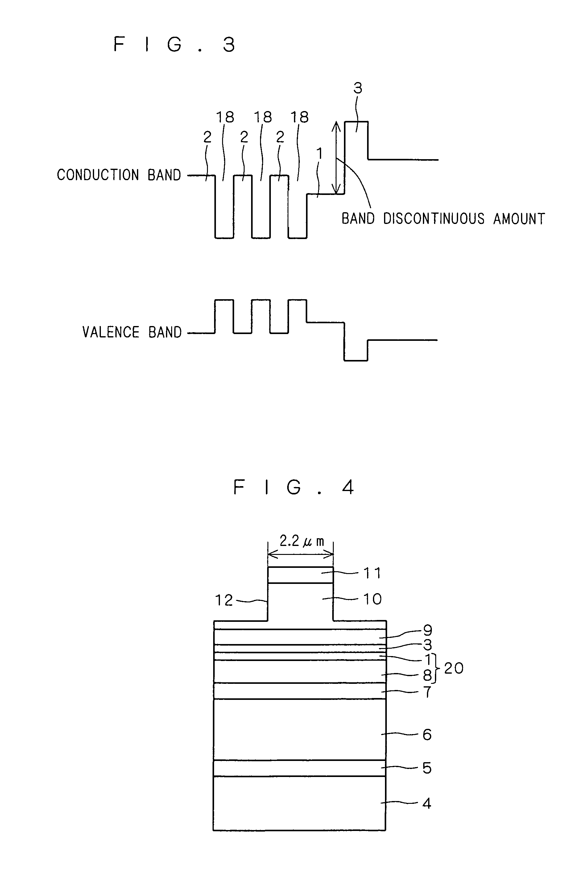
[0037]On the n-type GaN buffer layer 5, an n-type AlGaN clad layer (n-type clad layer) 6, an n-type GaN optical guide layer 7 as an n-side guide layer, an structure 20, a p-type AlGaN electron blocking layer 3 (electron blocking layer, blocking layer), a p-type GaN optical guide layer 9 as a p-side guide layer, a p-type AlGaN clad layer (p-type clad layer) 10, and a p-type GaN contact layer (p-type ...

second embodiment

[0084]A nitride-based semiconductor laser according to a second embodiment is similar to the first embodiment, except that the final barrier layer 1 is formed of a plurality of partial final barrier layers 13, 19 (not shown in FIG. 1).

[0085]Herein, the partial final barrier layer 13 is called a first barrier layer disposed closer to the n-type layers of the semiconductor laser, i.e., the n-side, and the partial barrier layer 19 is called a second barrier layer disposed closer to the p-side.

[0086]The first barrier layer 13 has a thickness of, for example, 10 nm, is made of InGaN having an In composition ratio of 0.02, and is formed on the active layer 8. On the first barrier layer 13, the second barrier layer 19 having a thickness of 10 nm and made of InGaN having an In composition ratio of 0.04 is formed.

[0087]Other configuration is the same as in the nitride-based semiconductor laser according to the first embodiment, and duplicate explanation is omitted.

[0088]FIG. 7 is a band diag...

third embodiment

[0101]In a nitride-based semiconductor laser according to a third embodiment, the final barrier layer 1 is made of InGaN of which In composition ratio increases continuously from 0.02 to 0.04 in the direction from the closest well layer 18 to the electron blocking layer 3.

[0102]Other configuration is the same as in the nitride-based semiconductor laser according to the first embodiment, and duplicate explanation is omitted.

[0103]FIG. 8 is a band diagram in the vicinity of the structure 20 of the nitride-based semiconductor laser according to this embodiment. As shown in FIG. 8, the band gap of the final barrier layer 1 decreases continuously approaching the electron blocking layer 3, and at the position contacting the electron blocking layer 3, the band gap is smaller than the band gap of the barrier layers 2.

[0104]The rate of electrons overflowing from electron blocking layer 3 is mostly determined by the band discontinuity in the conduction band at the contacting position of the f...


PUM


Abstract

A semiconductor light-emitting device which exhibits small threshold current, high differential efficiency, and good characteristics, by reducing electrons that overflow an electron barrier, trapping the electrons in an active layer. Of the barrier layers of an active layer, a final barrier layer, which is a barrier layer closest to a p side, is smaller in band gap energy than other barrier layers. Thus, as compared with a case where the final barrier layer has the same band gap energy as that of the other barrier layer, an energy band discontinuity (electron barrier) with an electron blocking layer can be made larger. As a result, overflow of electrons is reduced.

Description

BACKGROUND OF THE INVENTION[0001]1. Field of the Invention[0002]The present invention relates to a semiconductor light-emitting device using a nitride-based III-V group compound semiconductor.[0003]2. Description of the Background Art[0004]Recently, as a semiconductor laser which enables light emission in a range from a blue region to an ultraviolet region, which is required for making the density of an optical disc high, a nitride-based semiconductor laser using a nitride-based III-V group compound semiconductor has been intensively researched and developed, and has been already put in use.[0005]In the nitride-based semiconductor lasers reported so far, as an active layer structure, there has been frequently adopted a multiple quantum well structure with two or more well layers made of InGaN and three or more barrier layers made of InGaN having a smaller In composition ratio than that of the InGaN of the well layers (usually about 0.02) are laminated alternately.[0006]In the nitrid...

Claims


Application Information

Patent Timeline
Patent Type & Authority Patents(United States)
IPC IPC(8): H01L31/0352B82Y20/00H01S5/343
CPCB82Y20/00H01S5/34333H01S5/22H01L33/06H01S5/2009H01S5/3407H01S5/3415
Inventor KURAMOTO, KYOSUKE
Owner MITSUBISHI ELECTRIC CORP
Why Eureka
Try Eureka