Evaporator for capillary loop

a capillary loop and evaporator technology, applied in the field of heat transfer, can solve the problems of limited direct contact between the wick and the heated surface, the tendency of the vapor generated at the heat transfer surface to interfere with the heat transfer into and through the wick, and the pipe evaporator, etc., to achieve the effect of improving heat transfer, high permeability, and simplifying the construction of the evaporator

Active Publication Date: 2010-07-06
ADVANCED COOLING TECH
View PDF13 Cites 38 Cited by
  • Summary
  • Abstract
  • Description
  • Claims
  • Application Information

AI Technical Summary

Benefits of technology

[0008]Several structural variations can be added to enhance the performance of the simple cup of wick material. One such modification is selection of the sidewall wick thickness and pore size to accommodate different liquids within the capillary loop and different heat loads.
[0019]The present invention thereby provides a capillary loop evaporator that has improved heat transfer from the heat source to the evaporator wick, reduced likelihood of vapor blockage of the liquid supply, and particularly with the separated evaporator and reservoir, reduced parasitic heat loss to the reservoir.

Problems solved by technology

Basic limitations of the typical capillary loop evaporator are the limited direct contact between the wick and the heated surface, and the tendency of the vapor generated at the heat transfer surface to interfere with heat transfer into and through the wick.
Another disadvantage of the conventional loop heat pipe evaporator is its proximity and thermal transfer to the reservoir.
Still other problems arise in the difficulty of manufacturing capillary loop and loop heat pipe evaporators since they usually require cylindrical wicks with longitudinal grooves on the outer surface.

Method used


Image

  • Evaporator for capillary loop
  • Evaporator for capillary loop
  • Evaporator for capillary loop

Examples


Embodiment Construction

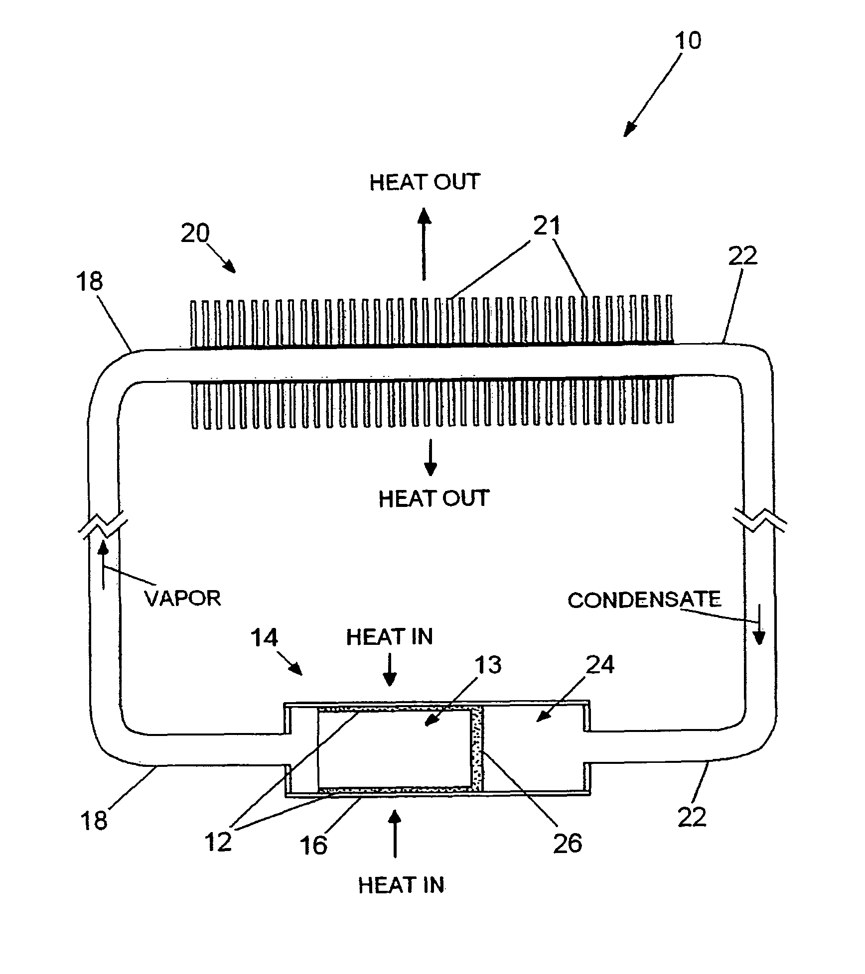
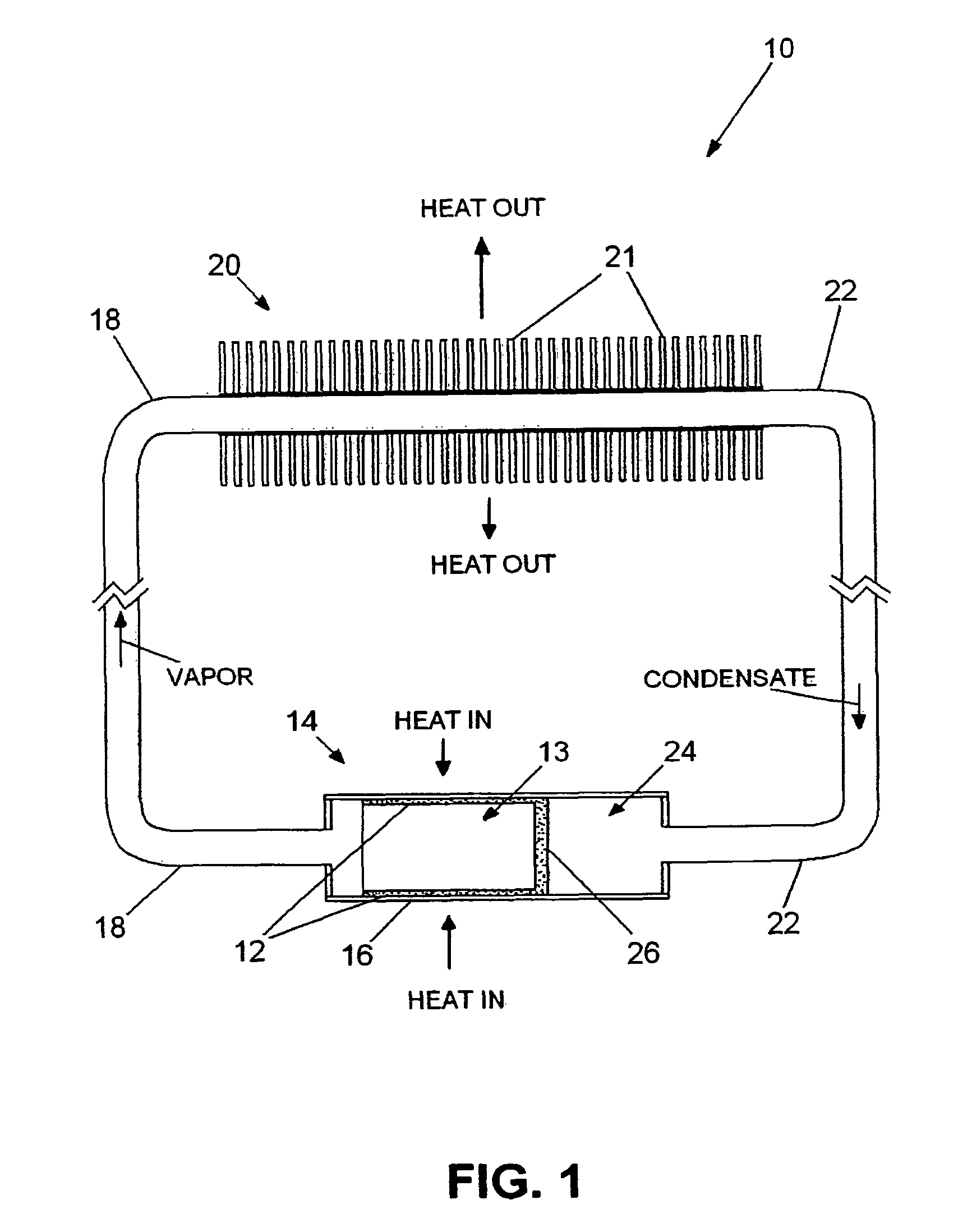
[0033]FIG. 1 is a schematic diagram of typical capillary loop 10 showing evaporator wick 12 of the preferred embodiment of the invention within evaporator 14. Evaporator wick 12 of FIG. 1 is a simple cup and is also shown in FIG. 2 in a perspective cut away view to better show the interior of evaporator 14. The important characteristic of evaporator wick 12 is that all the outer surfaces of its sidewalls are in intimate contact with heated walls 16 of the enclosure forming evaporator 14. This complete contact between evaporator wick 12 and heated enclosure walls 16 makes heat transfer and vaporization of the liquid within evaporator wick 12 much more effective, and the vapor generated moves through evaporator wick 12 into vapor space 13.

[0034]When capillary loop 10 is in operation, heat enters evaporator 14 and travels through evaporator enclosure wall 16 into wick 12 which is saturated with liquid. The heat causes the liquid to vaporize, and the vapor pressure moves the vapor out o...


PUM


Abstract

The apparatus is a capillary loop evaporator in which the vapor space is the internal volume of a cup shaped evaporator wick with sidewalls in full contact with the outer casing of the evaporator. Liquid is furnished to the wick through thicker wick wall sections, slabs protruding from the liquid-vapor barrier wick, eccentric wick cross sections, or tunnel arteries. The tunnel arteries can also be formed within heat flow reducing ridges protruding into the vapor space. The tunnel arteries can be fed liquid by bayonet tubes or cable arteries, and can be isolated from the heat source with regions of finer wick to impede vapor flow into the liquid. Tunnel arteries also enable separation of the evaporator and the reservoir for thermal isolation and structural flexibility. A wick within the reservoir aids collection of liquid in low gravity applications.

Description

BACKGROUND OF THE INVENTION[0001]This invention deals generally with heat transfer and more particularly with a capillary loop evaporator that has full thermal contact of the wick with the heat input surface.[0002]A capillary loop and a loop heat pipe are devices for transferring heat by the use of evaporation at the source of heat and condensation at the cooling location, and they eliminate some of the limitations of a simple heat pipe by separating the vapor and liquid movement into different conduits. Thus, liquid fed to an evaporator is evaporated and moves through a vapor transport line to the condenser, and condensate moves from the condenser to the evaporator through a liquid transport line. Typically, a liquid reservoir is constructed in close vicinity to the evaporator and a barrier wick separates the liquid in the reservoir from the vapor in the evaporator while moving liquid into the evaporator wick by capillary action.[0003]Prior art capillary loop and loop heat pipe eva...

Claims


Application Information

Patent Timeline
Patent Type & Authority Patents(United States)
IPC IPC(8): F28D15/00H05K7/20
CPCF28D15/0266F28D15/046
Inventor ANDERSON, WILLIAM G.SARRAF, DAVIDDUSSINGER, PETER M.HARTENSTINE, JOHN R.
Owner ADVANCED COOLING TECH
Why Eureka
Try Eureka