Process margin using discrete assist features

a technology of assist features and process margins, applied in the field of process margins using discrete assist features, can solve problems such as negative impact on system yield

Active Publication Date: 2010-07-06
GLOBALFOUNDRIES U S INC
View PDF15 Cites 109 Cited by
  • Summary
  • Abstract
  • Description
  • Claims
  • Application Information

AI Technical Summary

Benefits of technology

[0009]In accordance with one aspect of the subject invention, novel geometries for subresolution assist features are utilized to change the environment and thereby reduce variations in printed line width which otherwise might negatively impact the transfer of a mask pattern onto a wafer. In accordance with one or more aspects of the subject invention, light diffracted from the edges of the novel subresolution assist features placed near semi-isolated features provides a beneficial interaction with light associated with the semi-isolated feature. The resulting printed line width is more consistent with the printed line width produced by areas of the mask comprising higher feature density. Furthermore, the light diffracted from the novel subresolution assist features does not result in a partial exposure of a portion of a resist and thereby does not create an undesirable resist residue after removal of the resist layer.
[0011]In accordance with this aspect of the subject invention, the placement and dimensions of the discrete scatterbar segments can be selected such that the discretized scatterbars will not be printed onto the resist layer, and furthermore, can mitigate formation of resist residue that can limit yield on the resulting wafer. The placement of the discretized scatterbar facilitates decreasing in pitch to the optical system with respect to printing of adjacent features. The printed critical dimensions of the adjacent features are therefore more consistent with the critical dimensions achieved for the balance of the features of the mask. Furthermore, the undesirable formation of resist residue can be avoided as a result of the line-end pull back caused by diffraction of light at the ends of each discrete scatterbar segment.
[0012]In accordance with another aspect of the subject invention, discrete scatterbar segments are created utilizing “forbidden” pitches to avoid formation of resist residue. Forbidden pitches refer to pitches that can result in a degradation of the process window for a lithographic imaging system. The addition of assist features to alter the apparent density and pitch as seen by the projection system can result in a sudden reduction or downward spike in the process window for a given span of pitches. The pitch values where the process window has a downward spike and falls below a threshold value are referred to as forbidden pitches. These pitches are “forbidden” to be used in the layout of a desired pattern because of the undesirable reduction in the process window that such pitches can cause. However, in accordance with an aspect, placement of discrete scatterbar segments at forbidden pitches can provide the process benefits of improved critical dimension control for an adjacent feature and can also mitigate the creation of resist residue, which can otherwise have a deleterious affect on the yield of a resulting processed image.
[0014]In accordance with one aspect of the subject invention, discrete scatterbar segments are placed perpendicular to a wordline to maintain critical dimension control while avoiding the formation of resist residue. In one aspect, the discrete segments comprise a grating placed at a pitch consistent with a bitline pitch, which permits placement of discrete scatterbar segments directly above bitline contacts. In accordance with this aspect, the pitch of the elements comprising the grating is oriented in a direction perpendicular to the axis of a dipole illumination source at a pitch that need not be resolved by the imaging system. The dimensions of the grating elements can be such that they will not be printed or result in the formation of a resist residue.
[0015]In accordance with yet another aspect of the subject invention, the size, spacing and placement of the discrete scatterbar segments can be determined through simulation. The diffraction interactions of light passing through a mask are complex, and simulations can aid in determining an optimal placement of discrete scatterbar segments and for further determining a resulting depth of focus for the system.

Problems solved by technology

The presence of such a resist residue can negatively impact the yield of the system.
Furthermore, the light diffracted from the novel subresolution assist features does not result in a partial exposure of a portion of a resist and thereby does not create an undesirable resist residue after removal of the resist layer.

Method used


Image

  • Process margin using discrete assist features
  • Process margin using discrete assist features
  • Process margin using discrete assist features

Examples


Embodiment Construction

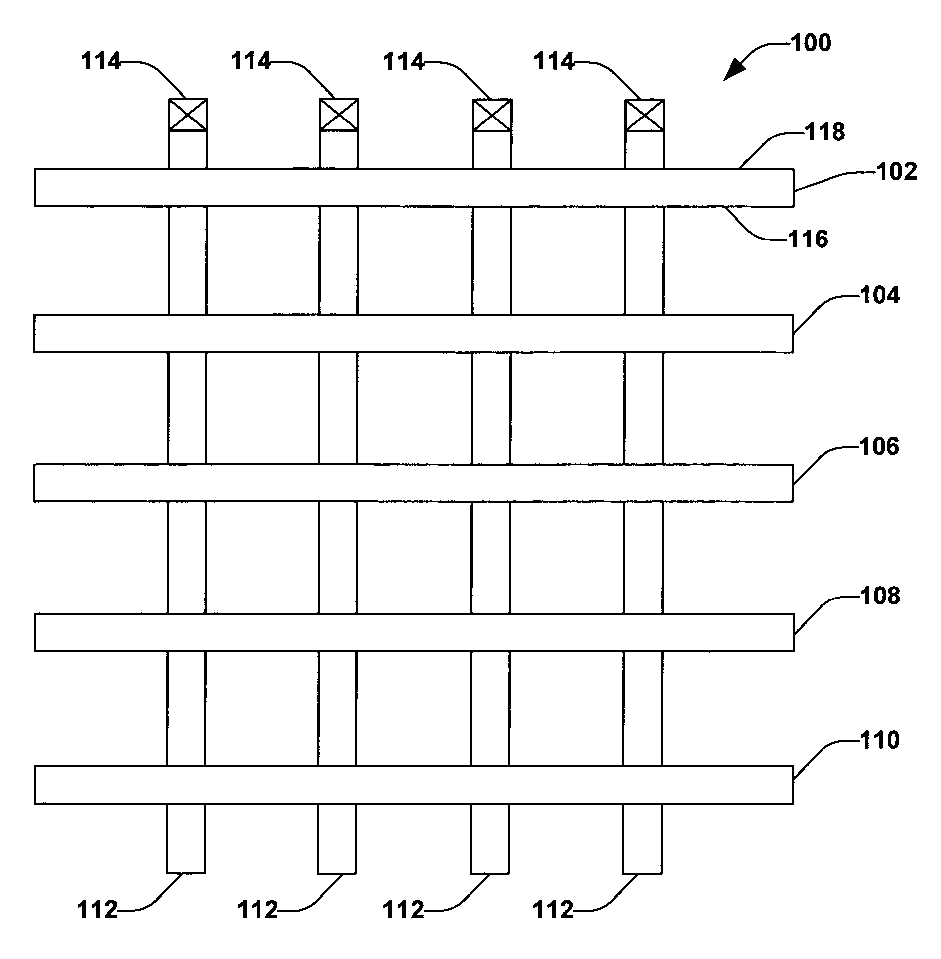
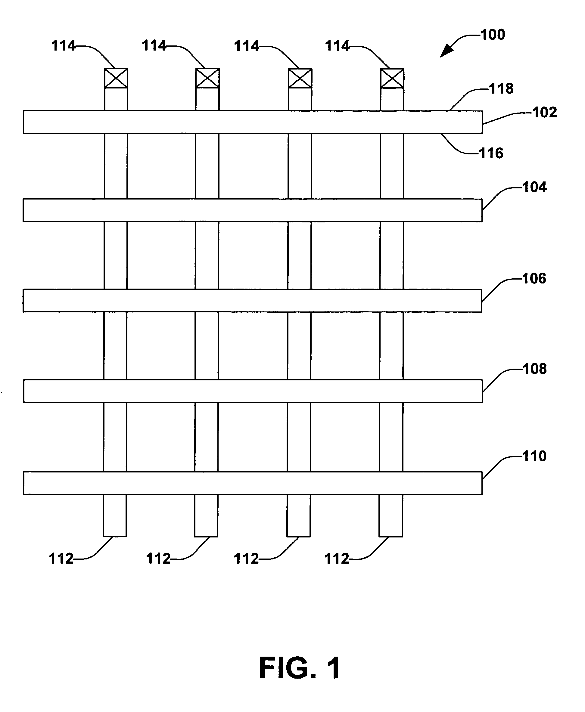
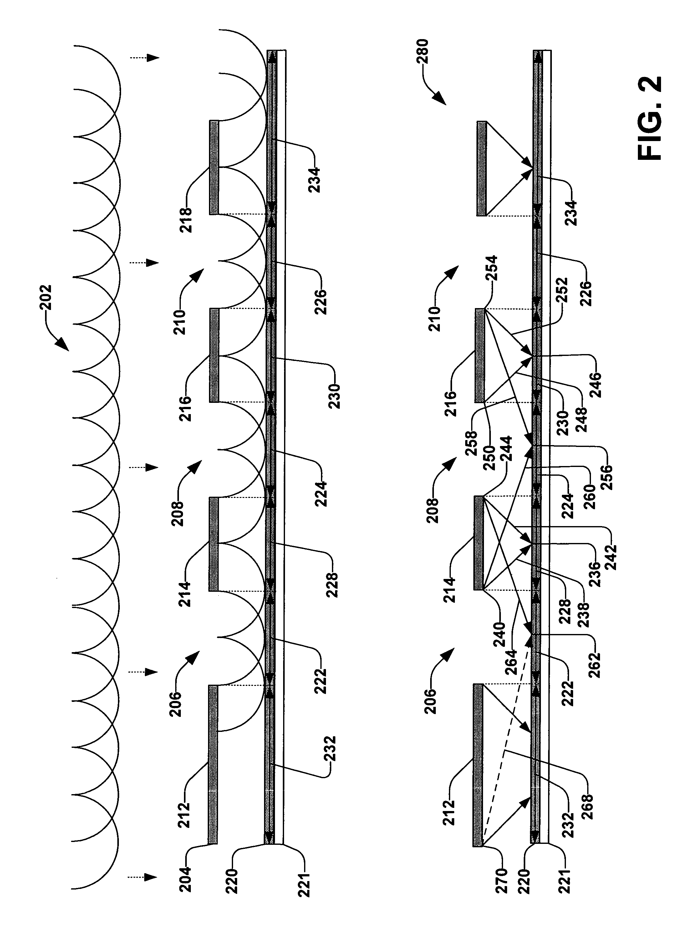
[0030]The invention will now be described with reference to the drawings, wherein like reference numerals are used to refer to like elements throughout. The invention will be described with reference to systems and methods that facilitate providing a discretized scatterbar that improves process margin. The discretized scatterbar provides the benefits of more consistent critical dimensions for semi-isolated features without the formation of a resist residue. It should be understood that the description of these exemplary aspects are illustrative and should not be taken in a limiting sense.

[0031]The term “component” can refer to a computer-related entity, either hardware, a combination of hardware and software, software, or software in execution. For example, a component can be a process running on a processor, a processor, an object, an executable, a thread of execution, a program and a computer. By way of illustration, both an application running on a server and the server can be co...


PUM

PropertyMeasurementUnit
wavelengthaaaaaaaaaa

Abstract

The subject invention provides a system and method for improving the process margin of a lithographic imaging system. The process margin improvement is achieved through the novel placement of discrete assist features and / or the use of forbidden pitches and specific pitch orientations. Novel geometries are utilized, which take advantage of line-end pull back and / or a lack of resolution of pitches perpendicular to an axis of a dipole illumination source. The strategic placement of a series of discrete scatterbar segments on a mask near positions of critical features, such as, for example, contacts, mitigates resist residue that can result from the use of a contiguous scatterbar.

Description

FIELD OF INVENTION[0001]The subject invention relates generally to semiconductor devices and, in particular, to a method of improving process margin of a lithographic imaging process through the use of discrete assist features.BACKGROUND OF THE INVENTION[0002]In the semiconductor industry, there is a continuing trend toward higher device densities. To achieve these high device densities there have been, and continue to be, efforts toward scaling down device dimensions (e.g., at sub-micron levels) on semiconductor wafers. In order to accomplish such densities, smaller feature sizes and more precise feature shapes are required. This can include width and spacing of interconnecting lines, spacing and diameter of contact holes, and surface geometry, such as corners and edges, of various features. The dimensions of and between such small features can be referred to as critical dimensions (CDs). Reducing CDs and reproducing more accurate CDs facilitates achieving higher device densities.[...

Claims


Application Information

Patent Timeline
Patent Type & Authority Patents(United States)
IPC IPC(8): G03F1/00
CPCG03F1/144G03F1/36G03F7/70425G03F7/70433G03F7/70491H01L21/67276
Inventor MATTHEW, ITTYSINGH, BHANWAR
Owner GLOBALFOUNDRIES U S INC
Why Eureka
Try Eureka