
Analog to digital converter using asynchronous pulse technology

a technology of analog-to-digital converter and asynchronous pulse, which is applied in the direction of code conversion, transmission system, instruments, etc., can solve the problems of no paper can study the transformation from analog to pulse domain and back, and no attempt to build an analog-to-digital converter

Inactive Publication Date: 2010-07-06
HRL LAB
View PDF13 Cites 31 Cited by
  • Summary
  • Abstract
  • Description
  • Claims
  • Application Information

AI Technical Summary

Benefits of technology

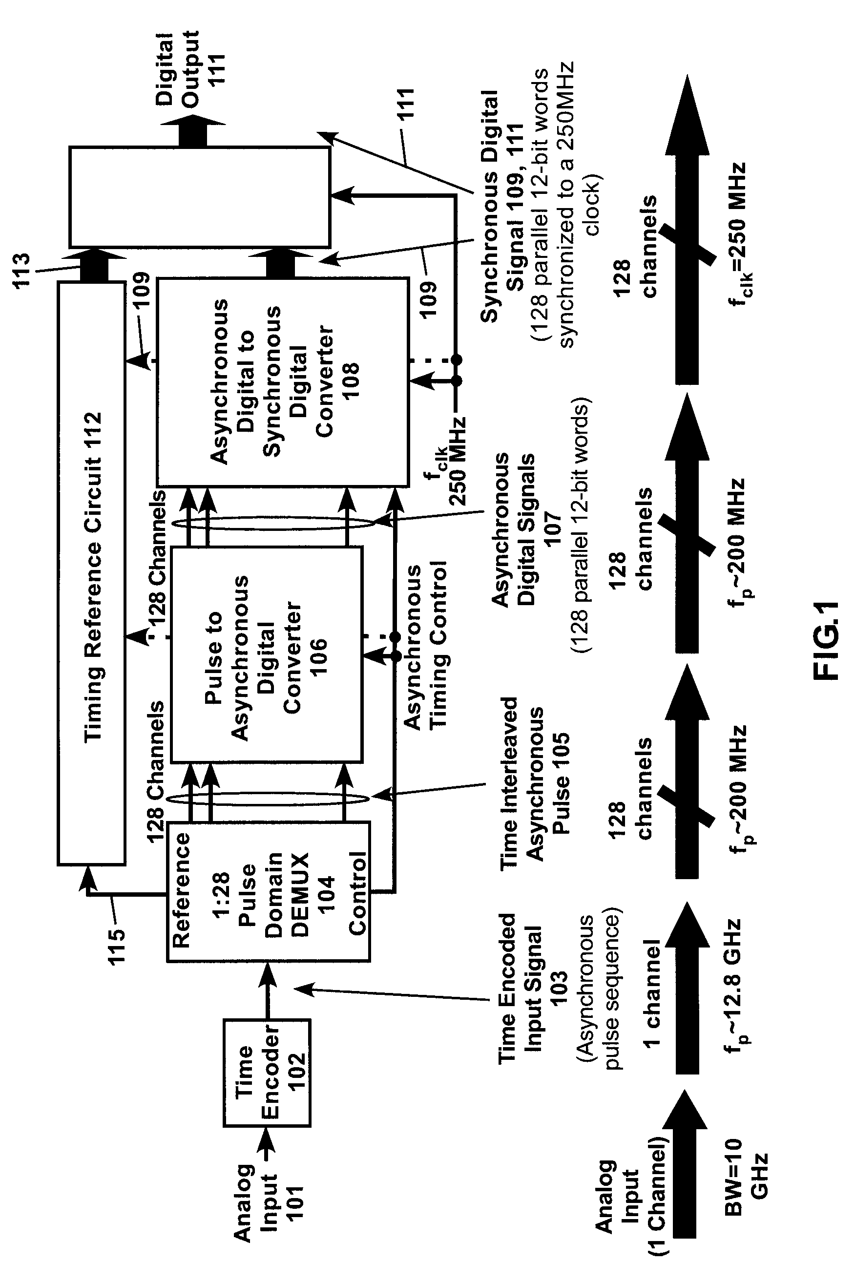
The patent describes an improved analog-to-digital converter architecture that uses pulse encoding and demultiplexing to achieve higher speed and resolution performance. The architecture includes a front end time encoder, a pulse asynchronous DeMUX circuit, a parallel pulse to asynchronous digital converter, an asynchronous digital to synchronous digital converter, and a timing reference circuit. The new architecture has been found to be tolerant of jitter and offsets in control signals, and can achieve ultra wide bandwidth and higher speed-resolution performance compared to existing ADCs. The patent also describes the features and components of the new architecture, including the time encoder, the pulse deMUX circuit, and the pulse to asynchronous digital converter. The technical effects of the patent include higher speed and resolution performance, improved tolerance to jitter and offsets, and mitigation of quantization errors.

Problems solved by technology

However, this paper is limited to study the transformation from analog domain into the pulse domain and back.
No attempt is made to build an analog-to-digital converter.
This simple direct sampling process introduces potentially large quantization errors that are only mitigated by significantly over-sampling the synchronous clock to respect the asynchronous pulse sequence or by using poly-phase samplers.

Method used


Image

  • Analog to digital converter using asynchronous pulse technology
  • Analog to digital converter using asynchronous pulse technology
  • Analog to digital converter using asynchronous pulse technology

Examples


Embodiment Construction

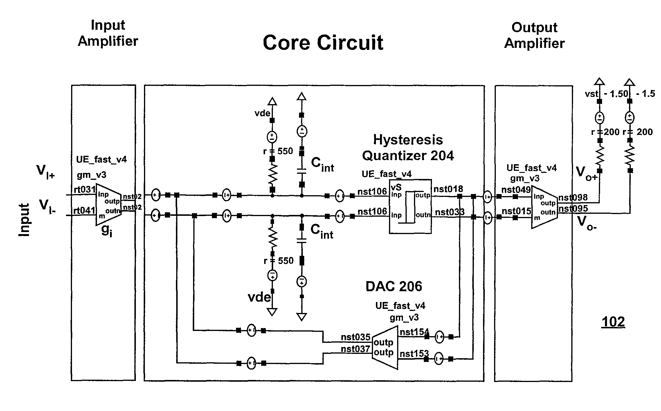
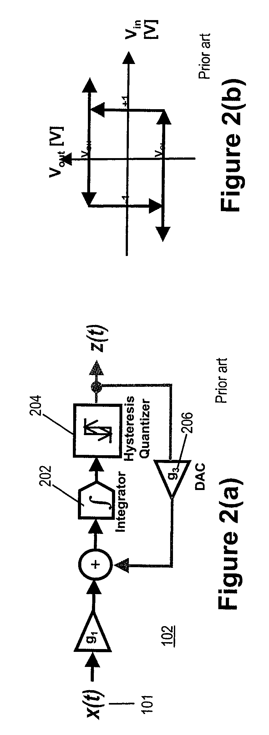
[0027]FIG. 1 shows an embodiment of the Analog-To-Digital Converter (ADC) Architecture 100 of the invention. The ADC architecture is composed of the following six elements: a time encoder 102; a pulse-domain demultiplexer 104; a pulse to asynchronous digital converter 106; an asynchronous digital to synchronous digital converter 108; a digital signal processor 110; and a timing reference circuit 112.

[0028]The time encoder 102 converts analog input data 101 into pulse data at its output. A pulse domain demultiplexer 104 has one input data channel and multiple (128 in this embodiment) parallel output data channels 105 which contain time interleaved asynchronous pulses representative of the analog input data 101.

[0029]A pulse to asynchronous digital converter 106 digitizes data in each of the parallel data channels from the pulse domain demultiplexer 104 into, in this embodiment, 12-bit words in each of the 128 channels. An asynchronous digital to synchronous digital converter 108 conv...


PUM


Abstract

A digital to analog converter includes a time encoder that converts an analog input signal into a asynchronous pulse sequence, a pulse asynchronous DeMUX circuit that converts the asynchronous pulse sequence into a parallel stream of pulse sequences at a relatively lower speed, a parallel pulse to asynchronous digital converter, an asynchronous digital to synchronous digital converter, a timing reference circuit to generate absolute time references, and a Digital Signal Processor. This architecture provides for analog to digital conversion based on pulse encoding with a parallel digitization scheme of the pulse encoded signal.

Description

CROSS-REFERENCE TO RELATED APPLICATION[0001]This application is a DIV of Ser. No. 11 / 726,484 filed on Mar. 22, 2007, now U.S. Pat. No. 7,515,084 which under 35 U.S.C. Section. 119(e) to U.S. Provisional Patent Application Ser. No. 60 / 764,866, “ADC Provisional Patent Application,” by Carl Grace, filed Feb. 2, 2006. The subject matter of the foregoing is incorporated herein by reference in its entirety.TECHNICAL FIELD[0002]This disclosure relates of an analog-to-digital converter architecture. It is based on encoding the analog data into an asynchronous time encoded pulse signal and then converting the pulse time encoded signal into a parallel digital signal.BACKGROUND INFORMATION[0003]The architecture of the disclosed system is composed of: (1) a front end time encoder that converts at high speed an analog input signal into a asynchronous pulse sequence, (2) a pulse asynchronous DeMUX circuit that converts the high speed asynchronous pulse sequence into a parallel stream of pulse seq...

Claims


Application Information

Patent Timeline
Patent Type & Authority Patents(United States)
IPC IPC(8): H03M1/50
CPCH03M3/47H03M3/432
Inventor CRUZ-ALBRECHT, JOSEPETRE, PETERJENSEN, JOSEPH F.
Owner HRL LAB
Learn More