Electronic control apparatus

a control apparatus and electronic technology, applied in the field of electronic control apparatus, can solve the problems of poor assembly, high production cost, difficult sealing of the main, etc., and achieve the effect of improving the reliability of electrical connections and reducing the size and cost of production

Inactive Publication Date: 2010-07-06
MITSUBISHI ELECTRIC CORP
View PDF19 Cites 17 Cited by
  • Summary
  • Abstract
  • Description
  • Claims
  • Application Information

AI Technical Summary

Benefits of technology

[0013]Accordingly, the present invention is intended to obviate the problems as referred to above, and has for its object to provide an electronic control apparatus and a production method therefor in which some parts are eliminated so as to reduce the size and the cost of production thereof, while improving the reliability of electrical connection.
[0014]Another object of the present invention is to provide an electronic control apparatus and a production method therefor which can be improved in the sealing performance (tightness) and the assembling efficiency.
[0017]With the electronic control apparatus and the method of producing the same as defined above according to the present invention, it is possible to reduce the size and the production cost of the electronic control apparatus, as well as to improve the reliability of electrical connection, the sealing performance, the assembling efficiency, etc.

Problems solved by technology

Also, there is another problem.
The power board, the housing and the control board are covered with the casing which has been press molded from the metal plate, so it is difficult to seal the main body of the apparatus, and in order to mount the apparatus on the engine room of a vehicle, a device of a sealed structure is separately required so as to prevent water from being infiltrated into the apparatus main body due to the pour water thereof, so separate production processes have to be used depending upon whether such a sealing device is required or not.
Further, in the electronic control apparatus described in the second patent document, there is the following problem.
That is, to prevent the infiltration of water into the apparatus main body, the rubber rings for sealing are needed, and the cost for production becomes high.
In addition, there is also another problem.
When the rubber rings with small rigidity are inserted into the groove formed in the heat sink and the groove formed in the housing, respectively, the time and effort are required, thus resulting in poor assemblability.

Method used


Image

  • Electronic control apparatus
  • Electronic control apparatus
  • Electronic control apparatus

Examples


embodiment 1

[0028]In this embodiment, description will be made by taking, as an example, an electronic control apparatus used in an electric power steering system that serves to assist a steering system of a vehicle by means of the rotational force of an electric motor.

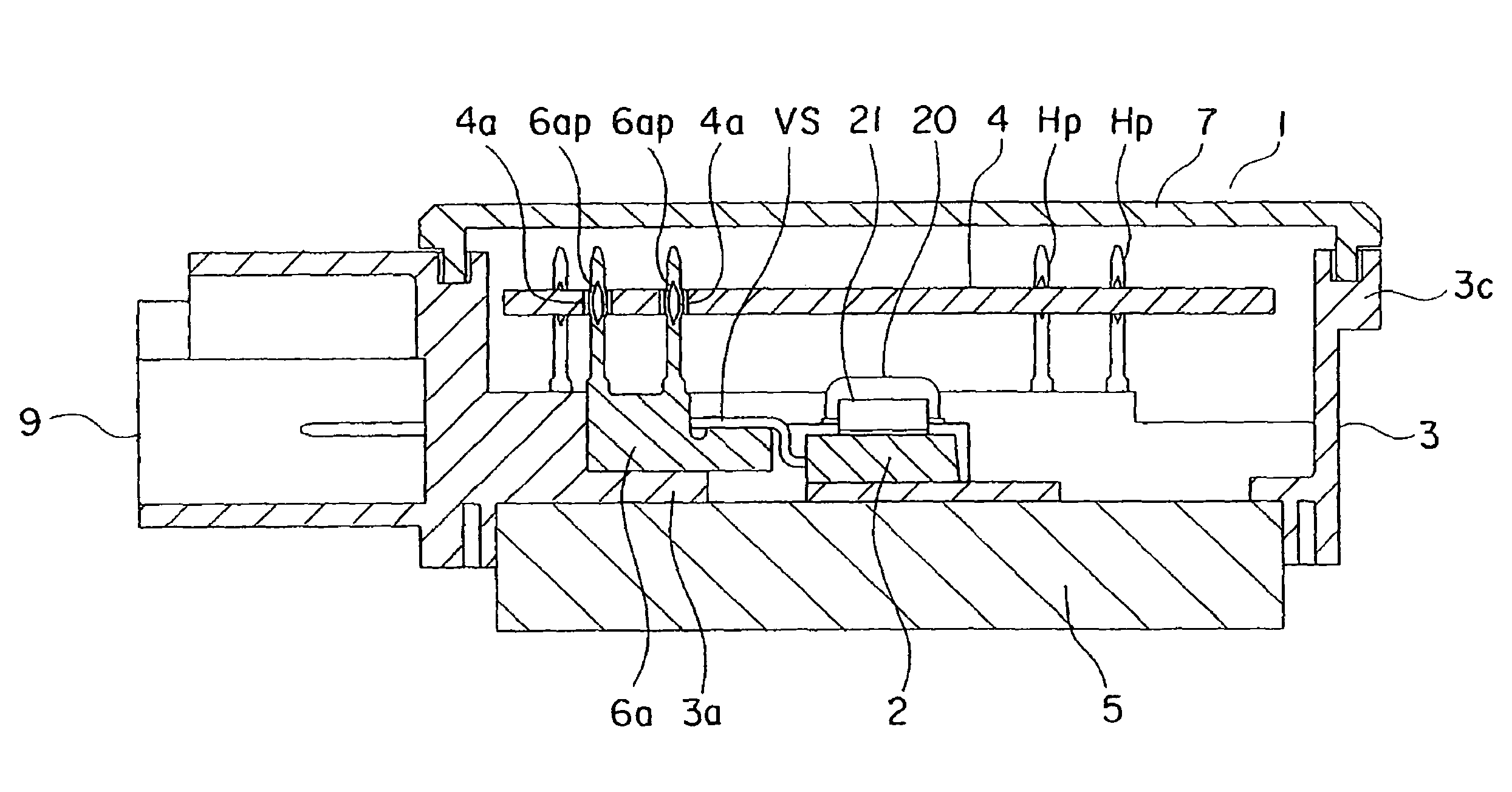
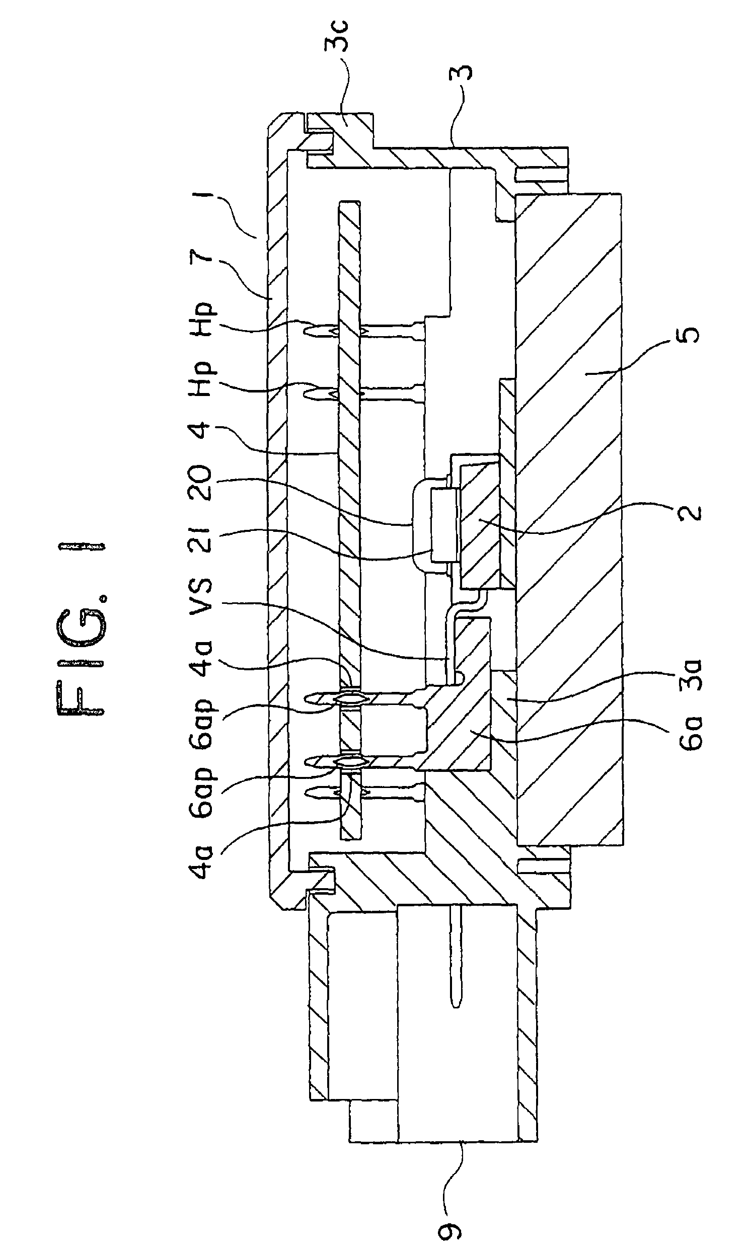
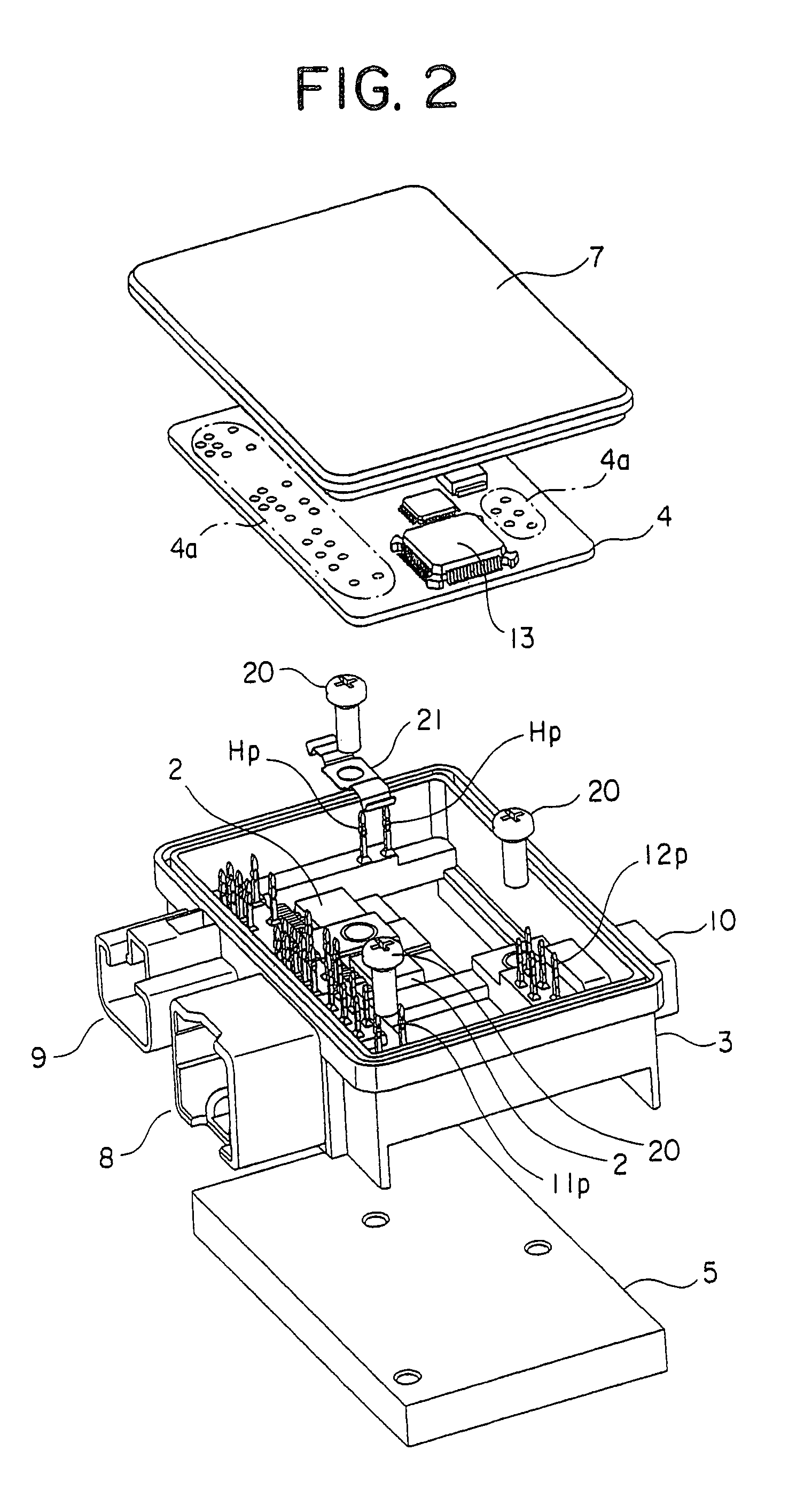
[0029]Referring to the drawings and first to FIG. 1, there is shown, in cross section, an electronic control apparatus according to a first embodiment of the present invention. FIG. 2 is an exploded perspective view showing the electronic control apparatus in FIG. 1. FIG. 3 is a block diagram showing an electric power steering system in FIG. 1. FIG. 4 is a perspective view showing the essential portions of the electronic control apparatus of FIG. 1.

[0030]The electronic control apparatus 1 includes: a housing 3 made of an insulating resin and having a pair of opening portions at opposite ends thereof; a heat sink 5 made of aluminum and attached to one end of the housing 3; semiconductor switching elements 2 that are mounted on the...

embodiment 2

[0098]FIG. 8 shows, in cross section, an electronic control apparatus 1 according to a second embodiment of the present invention.

[0099]In this second embodiment, a groove 30 is formed between an inner peripheral surface of the housing 3 and an outer peripheral surface of the heat sink 5, and an adhesive or bonding resin in the form of a silicon bonding material 31 is filled into the groove 30.

[0100]In addition, the vehicle connector 8, the motor connector 9 and the sensor connector 10 of the first embodiment are changed to corresponding connectors of the waterproof type, respectively, which are integrally molded with the housing 3.

[0101]Though not illustrated, a respiration or breathing hole for providing fluid communication between the inside and the outside of the electronic control apparatus 1 is formed through the housing 3, and a water-repellent filter, which permits the passage of air but prevents the passage of water therethrough, is mounted in the respiration hole.

[0102]The...


PUM

PropertyMeasurementUnit
thicknessaaaaaaaaaa
thicknessaaaaaaaaaa
widthaaaaaaaaaa

Abstract

An electronic control apparatus can be reduced in size and cost by eliminating certain component parts such as a power board, etc. The apparatus includes a housing, a heat sink, semiconductor switching elements having terminals and mounted on the heat sink, a circuit board arranged in opposition to the heat sink, conductive plates connecting between the circuit board and the semiconductor switching elements, and a cover receiving the semiconductor switching elements and the circuit board in cooperation with the heat sink. The conductive plates have the press-fit terminal portions press-fitted into the through holes in the circuit board, and the individual conductive plates are arranged along a lead-out direction in which the individual terminals of the semiconductor switching elements lead out, and are bonded to the individual terminals.

Description

BACKGROUND OF THE INVENTION[0001]1. Field of the Invention[0002]The present invention relates to an electronic control apparatus used in an electric power steering system for providing an assist force to a steering system of a vehicle by means of the rotational force of an electric motor.[0003]2. Description of the Related Art[0004]In the past, there has been known an electronic control apparatus in which a semiconductor switching element (FET), being a power device, is mounted on a metal substrate, and at the same time, a connecting member for electrically connecting between the metal substrate and parts outside the metal substrate is mounted on the metal substrate.[0005]For example, an electronic control apparatus described in a first patent document (Japanese patent No. 3644835) includes a power board on which a bridge circuit comprising semiconductor switching elements are mounted for switching a current supplied to an electric motor, a housing with conductive plates, etc., inse...

Claims


Application Information

Patent Timeline
Patent Type & Authority Patents(United States)
IPC IPC(8): H05K7/20H01L23/34F28F7/00H01B9/06
CPCH05K3/32H05K7/20509H05K7/20854H05K3/308H05K3/328H05K2201/10166H05K2201/10295H01L2924/0002H05K2201/105H05K2201/1059H05K2201/10962H01L2924/00B60R16/02B60R16/023B62D5/04
Inventor TOMINAGA, TSUTOMUKIMATA, MASAHIROKIFUKU, TAKAYUKIAKIYAMA, SHUZOFUJIMOTO, TADAYUKI
Owner MITSUBISHI ELECTRIC CORP
Why Eureka
Try Eureka