
Equipment and duct liner insulation and method

a technology of duct liner and equipment, applied in the direction of ducting arrangement, lighting and heating apparatus, heating types, etc., to achieve the effect of reducing sound transmission, enhancing air flow resistance, and low operating cos

Active Publication Date: 2010-07-13
JOHNS MANVILLE CORP
View PDF2 Cites 6 Cited by
  • Summary
  • Abstract
  • Description
  • Claims
  • Application Information

AI Technical Summary

Benefits of technology

[0006]To minimize locations where dust, dirt particles, bacteria, mold and the like can collect on the resilient liner insulation of the present invention; to provide the resilient liner insulation of the present invention with a tough, durable, puncture resistant, smooth airstream surface for an efficient, low operating cost, air conditioning system; and to provide the resilient liner insulation of the present invention with an enhanced air flow resistance that reduces sound transmission through the liner, the resilient liner insulation of the present invention has a smooth, tough, durable, puncture resistant, low porosity airstream surface. The low porosity airstream surface of the resilient insulation liner is formed on the polymeric fiber insulation blanket core by melting and consolidating polymeric fibers at and adjacent a major surface of the insulation blanket core to form a low porosity surface layer on the major surface of the insulation blanket core or by forming a single or multilayered low porosity acrylic surface coating layer on the major surface of the insulation blanket core. Preferably, the permeability of the surface layer is selected to provide the polymeric fiber liner insulation with a higher noise reduction coefficient than an identical polymeric fiber insulation blanket without the surface layer and preferably, the surface layer of the first major surface of the liner insulation has a porosity of between 200 and 1000 Mks Rayls as measured by ASTM test C522-87.

Problems solved by technology

However, to be considered for such applications, any polymeric fiber liner insulation must meet certain performance standards and be cost competitive with the glass fiber liner insulations currently being used for such applications.

Method used


Image

  • Equipment and duct liner insulation and method
  • Equipment and duct liner insulation and method

Examples


Embodiment Construction

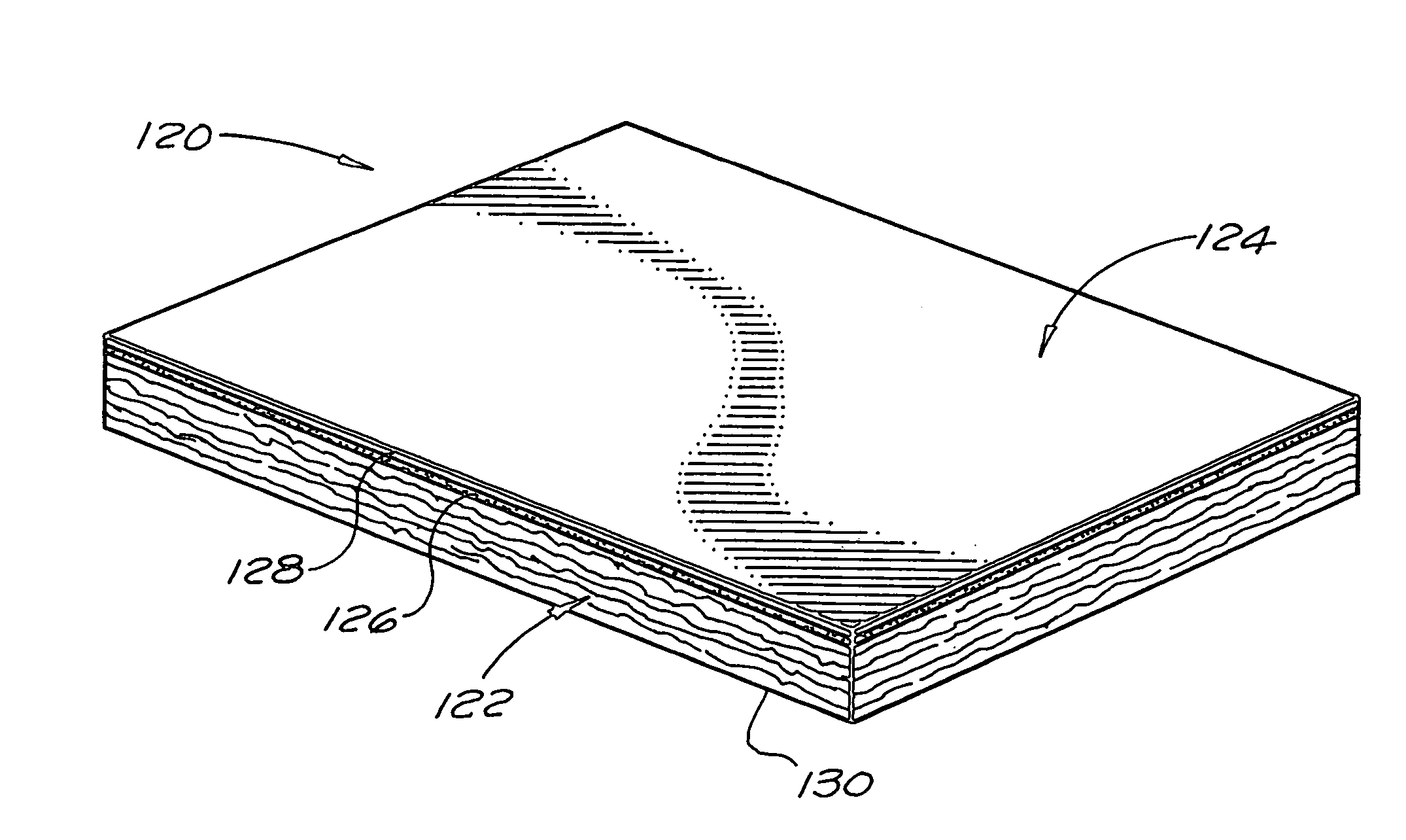
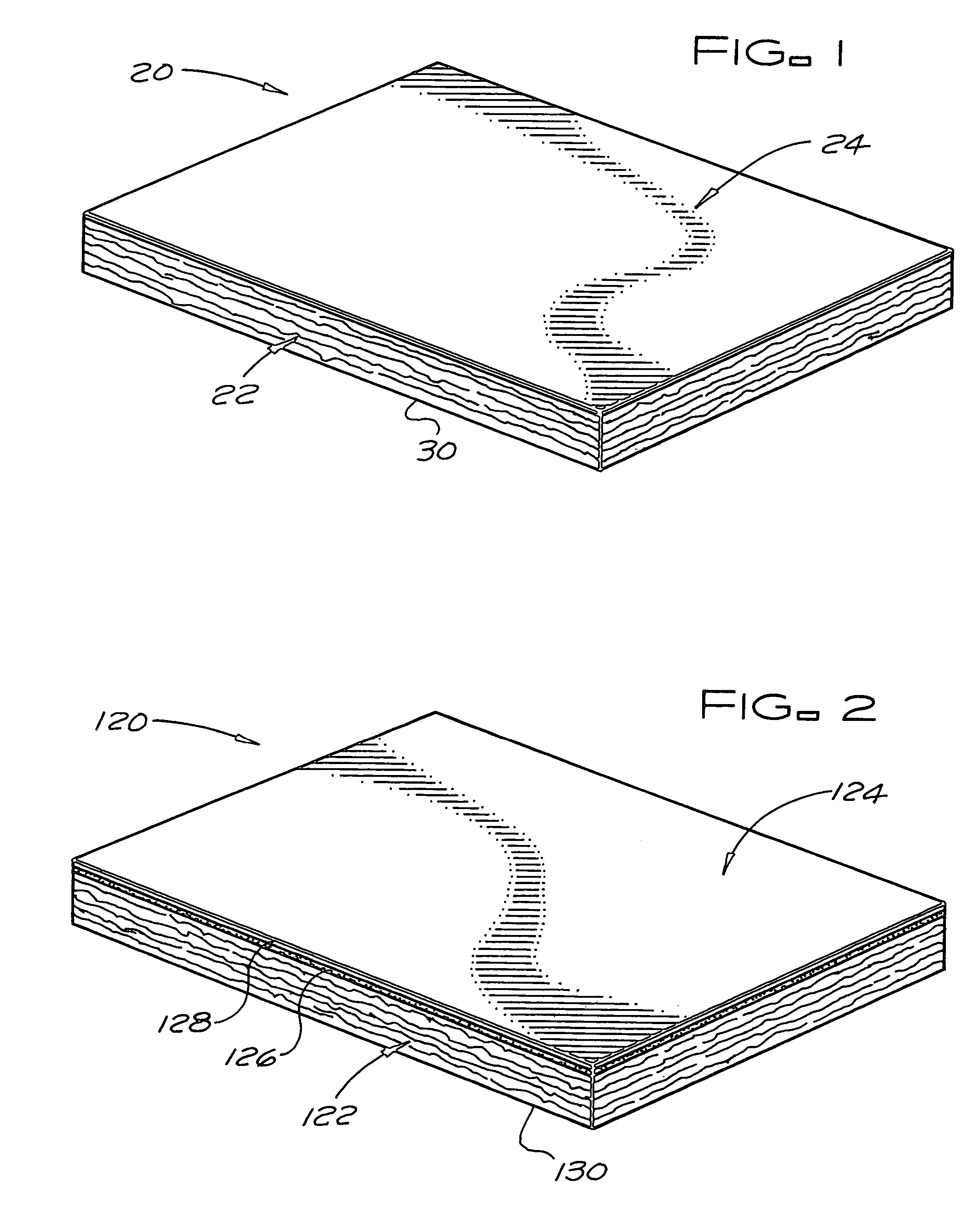
[0011]The resilient liner insulation 20 of the present invention includes a resilient polymeric fiber insulation blanket core 22 and a low porosity or fluid impervious surface layer 24 that forms a major surface of the resilient liner insulation. The surface layer 24 is a solidified layer of melted core fibers. The resilient liner insulation 120 of the present invention includes a resilient polymeric fiber insulation blanket core 122 and a low porosity or fluid impervious surface layer 124 that forms a major surface of the resilient liner insulation. Preferably, for cost savings, the surface layer 124 is a single coating layer. However, optionally, for certain applications requiring such a surface layer, the surface layer 124 of the resilient liner insulation 120 may be a multilayered coating of two or more layers, e.g. layers 126 and 128. The resilient liner insulations 20 and 120 both exhibit a flame spread / smoke developed index of ≦ 25 / 50.

[0012]The insulation blanket cores 22 and...


PUM

PropertyMeasurementUnit
lengthaaaaaaaaaa
lengthaaaaaaaaaa
thicknessaaaaaaaaaa

Abstract

A polymeric fiber liner insulation includes of a resilient, insulation blanket core of randomly oriented entangled fibers with between 60% and 90% by weight of the fibers being standard polymeric fibers and / or flame retardant polymeric fibers and between 10% and 40% by weight of the fibers being polymeric lofting and bonding fibers. The first major surface the liner insulation has a low porosity or air and / or liquid impervious surface layer. The surface layer is formed by melting and consolidating fibers at and adjacent the first major surface of the blanket core or by coating the first major surface of the blanket core with a polymeric coating. The liner insulation exhibits a flame spread / smoke developed index of ≦ 25 / 50.

Description

[0001]This application is a division of application Ser. No. 09 / 966,020, filed Sep. 28, 2001 now U.S. Pat. No. 6,797,653.BACKGROUND OF THE INVENTION[0002]The present invention relates to a resilient, liner insulation with a polymeric fiber insulation blanket core and to a method of making the resilient liner insulation. The resilient liner insulation exhibits a flame spread / smoke developed index per ASTM E-84-00a tunnel test of ≦ 25 / 50 and is especially suited for use as equipment and duct liner insulation for HVAC systems.[0003]Glass fiber thermal and acoustical liner insulations are frequently used to line the equipment housings (the housings for air conditioning units, primary fans, etc.) and the air ducts of heating ventilating and air conditioning systems (HVAC systems) to control thermal and / or noise transmission through the walls of these housings and ducts. Glass fiber thermal and acoustical liner insulations are also frequently used to wrap or encase equipment such as dishw...

Claims


Application Information

Patent Timeline
Patent Type & Authority Patents(United States)
IPC IPC(8): B29C59/00F24F13/24F24F13/02F16L59/02D04H1/46D06N7/00D06N3/04D06N3/00
CPCD04H1/46D06N3/042F16L59/026F24F13/0263F16L59/029D06N2209/128D06N2209/125D06N2209/067F24F2221/30Y10T442/20Y10T442/2139Y10T442/2213Y10T442/2631Y10T442/637Y10T442/641Y10T442/659Y10T442/674Y10T442/69Y10T442/696Y10T442/697
Inventor FAY, RALPH MICHAEL
Owner JOHNS MANVILLE CORP
Learn More