
Apparatus for working and observing samples and method of working and observing cross sections

a technology for working and observing samples, applied in the field of apparatus for working and observing cross sections, can solve the problems of maintaining position precision, etc., and achieve the effect of maintaining precision, efficient exchange, and large cross sections being efficiently worked

Active Publication Date: 2010-07-13
HITACHI HIGH TECH SCI CORP
View PDF11 Cites 2 Cited by
  • Summary
  • Abstract
  • Description
  • Claims
  • Application Information

AI Technical Summary

Benefits of technology

The present invention proposes an apparatus and method for working and observing samples by using a charged particle beam and a mask. The apparatus includes a sample plate for placing the sample, a first ion beam lens barrel capable of irradiating the sample with a beam, a mask-moving mechanism for adjusting the position of the mask, a charged particle beam lens barrel capable of scanning a focused beam of charged particles, and detection means for detecting a secondarily generated substance generated by the charged particles. The method involves adjusting the position of the mask, etching the sample with the first ion beam, and observing the cross section of the sample by detecting the secondarily generated substance. The technical effects of the invention include improved accuracy in positioning the mask and cross section of the sample, reduced damage to the sample, and improved observation of the cross section. Additionally, the invention provides a second ion beam lens barrel and a mask-exchanging mechanism for further improvement.

Problems solved by technology

In this case, it can be contrived to work the cross section by a mechanical method without, however, able to maintain precision of position on the cross section.

Method used


Image

  • Apparatus for working and observing samples and method of working and observing cross sections
  • Apparatus for working and observing samples and method of working and observing cross sections
  • Apparatus for working and observing samples and method of working and observing cross sections

Examples


first embodiment

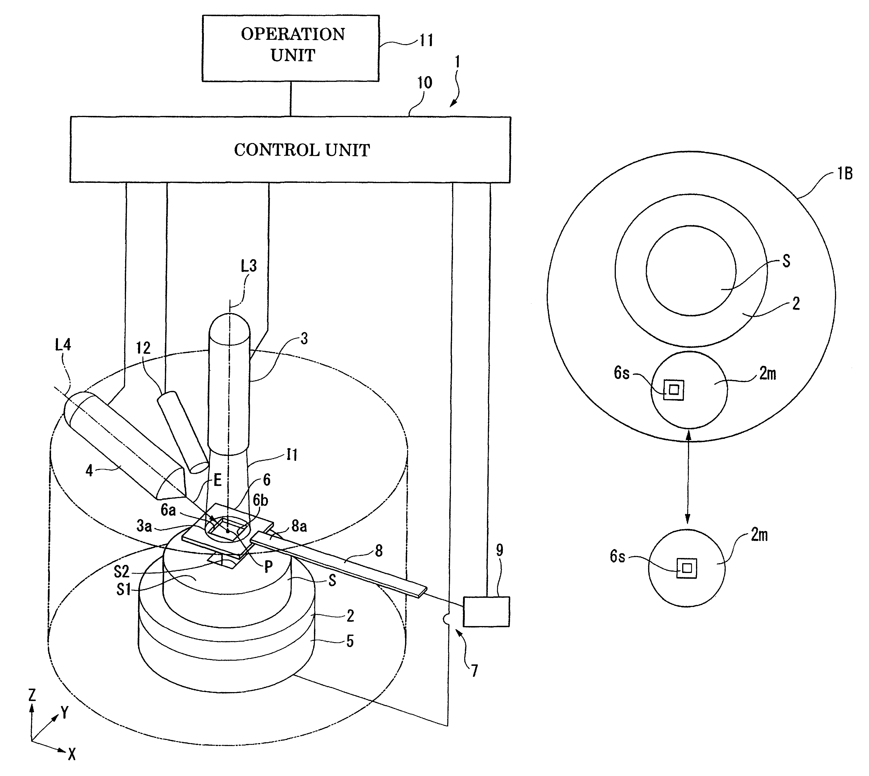
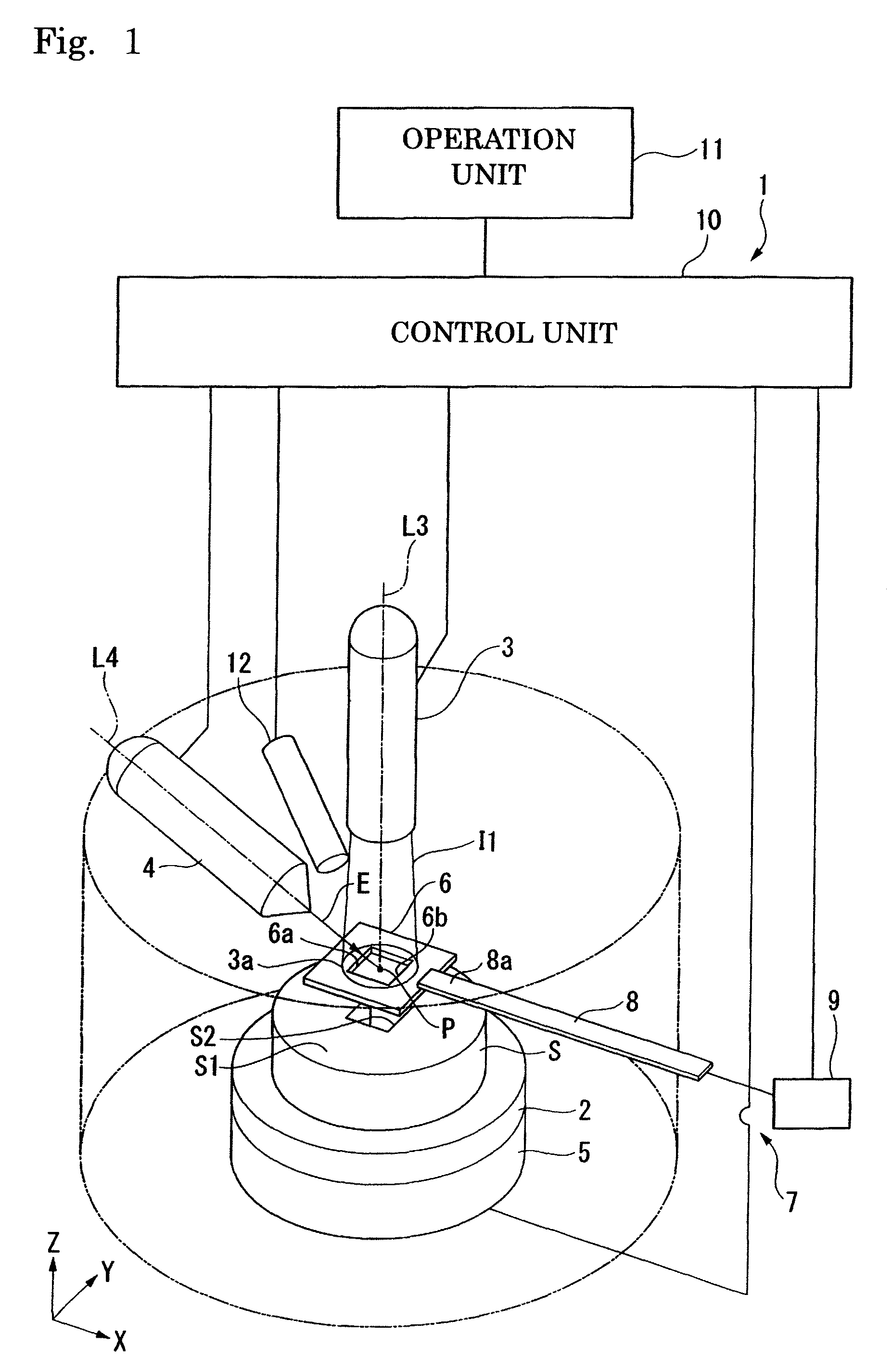
[0035]FIG. 1 illustrates a first embodiment according to the invention.

[0036]Referring to FIG. 1, an apparatus 1 for working and observing samples includes a sample plate 2 for placing a sample S, a first ion beam lens barrel 3 capable of irradiating a first ion beam I1, and an electron beam lens barrel 4 which is a charged particle beam lens barrel capable of irradiating an electron beam E focused as a charged particle beam. A five-axis stage 5 is provided at a lower portion of the sample plate 2. The five-axis stage 5 is capable of sliding the sample S placed on the sample plate 2 in a Z-axis direction in which the first ion beam I1 is irradiated, and in an X-axis direction and in a Y-axis direction nearly at right angles with the Z-axis, and is allowed to rotate about the Y-axis and the Z-axis.

[0037]If described in further detail, the first ion beam lens barrel 3 includes an argon ion source and a xenon ion source as ion sources, and is capable of irradiating an inert ion beam as...

second embodiment

[0050]FIG. 3 illustrates a second embodiment of the invention. In this embodiment, the members common to the members used in the above embodiment are denoted by the same reference numerals but their description is not repeated.

[0051]Referring to FIG. 5, an apparatus 20 for working and observing samples of this embodiment is further provided with a second ion beam lens barrel 21 and a gas introduction mechanism 22. The second ion beam lens barrel 21 is capable of irradiating a second ion beam I2 focused with an electric current smaller than that for the first ion beam I1. The second ion beam I2 is a focused ion beam using, for example, gallium ions as an ion source. The second ion beam lens barrel 21 is capable of scanning the second ion beam I2 within the irradiation range 3a of the first ion beam I1 with the center axis L21 as a center, the center axis L21 being so set as to intersect the first ion beam lens barrel 3 and the electron beam lens barrel 4 at a point P of intersection....


PUM


Abstract

The apparatus for working and observing samples comprises a sample plate on which a sample is to be placed; a first ion beam lens barrel capable of irradiating a first ion beam over a whole predetermined irradiation range at one time; a mask that can be arranged between the sample plate and the first ion beam lens barrel, and shields part of the first ion beam; mask-moving means capable of moving the mask; a charged particle beam lens barrel capable of scanning a focused beam of charged particles in the range irradiated with the first ion beam; and detection means capable of detecting a secondarily generated substance.

Description

RELATED APPLICATIONS[0001]This application claims priority under 35 U.S.C. §119 to Japanese Patent Application Nos. JP2007-061472 filed Mar. 12, 2007 and JP2008-058467 filed Mar. 7, 2008, the entire contents of which are hereby incorporated by reference.BACKGROUND OF THE INVENTION[0002]This invention relates to an apparatus for working and observing cross sections of samples by irradiating the samples with an ion beam, and a method of working and observing cross sections.[0003]A method of observing cross sections has heretofore been carried out by forming a cross section in the sample by etching the sample by the irradiation with an ion beam. For example, a method has been proposed for forming a cross section by using a focused ion beam lens barrel and by irradiating a focused ion beam on a predetermined position for forming the cross section without using a mask (e.g., see Japanese Patent No. 3117836). According to this method, the cross section that is formed is irradiated with a ...

Claims


Application Information

Patent Timeline
Patent Type & Authority Patents(United States)
IPC IPC(8): G21K5/04G21K5/10
CPCH01J37/3056G01N1/286H01J2237/31745
Inventor FUJII, TOSHIAKITAKAHASHI, HARUOTASHIRO, JUNICHI
Owner HITACHI HIGH TECH SCI CORP
Learn More