Broadband optical metrology with reduced wave front distortion, chromatic dispersion compensation and monitoring

a wideband optical metrology and chromatic dispersion compensation technology, applied in optical radiation measurement, instruments, spectrophotometry/monochromators, etc., can solve the problem of increasing wave front distortion, prior art systems are not able to combine low wavelength distortion constraints, and cannot examine samples with small spots exhibiting low wave front distortion. , to achieve the effect of reducing wave front distortion, and reducing chromatic distortion

Inactive Publication Date: 2010-07-13
N & K TECH
View PDF27 Cites 13 Cited by
  • Summary
  • Abstract
  • Description
  • Claims
  • Application Information

AI Technical Summary

Benefits of technology

[0007]In view of the above prior art limitations, it is an object of the present invention to provide an apparatus and method for examining samples with a small beam spot that exhibits reduced wave front distortion. Specifically, it is an object of the invention to provide appropriate reflective optics and spatial filtering to achieve reduced wave front distortion and reduced chromatic distortion.
[0008]It is another object of the invention to ensure that the apparatus and method can be employed in optical reflectance as well as combined reflectance and transmittance measurements of bulk samples as well as samples with miniature features, such as semiconductor wafers bearing photolithographically produced integrated circuits.
[0009]It is a further object to provide an apparatus and method for examining samples with a transmitted broadband beam that is compensated for chromatic dispersion manifesting in chromatic walk-off or spreading of the transmitted beam as well as chromatic aberration.
[0010]It is still another

Problems solved by technology

The large bandwidth or wavelength range Δλ of the radiation used in these test beams imposes a set of constraints on the optical system and on a number of its operating parameters.
The most important constraints are the increasing wave front distortion encountered when employing refractive optics in apparatus for these applications as well as chromatic dispersion.
Unfortunately, although some of t

Method used


Image

  • Broadband optical metrology with reduced wave front distortion, chromatic dispersion compensation and monitoring
  • Broadband optical metrology with reduced wave front distortion, chromatic dispersion compensation and monitoring
  • Broadband optical metrology with reduced wave front distortion, chromatic dispersion compensation and monitoring

Examples


Embodiment Construction

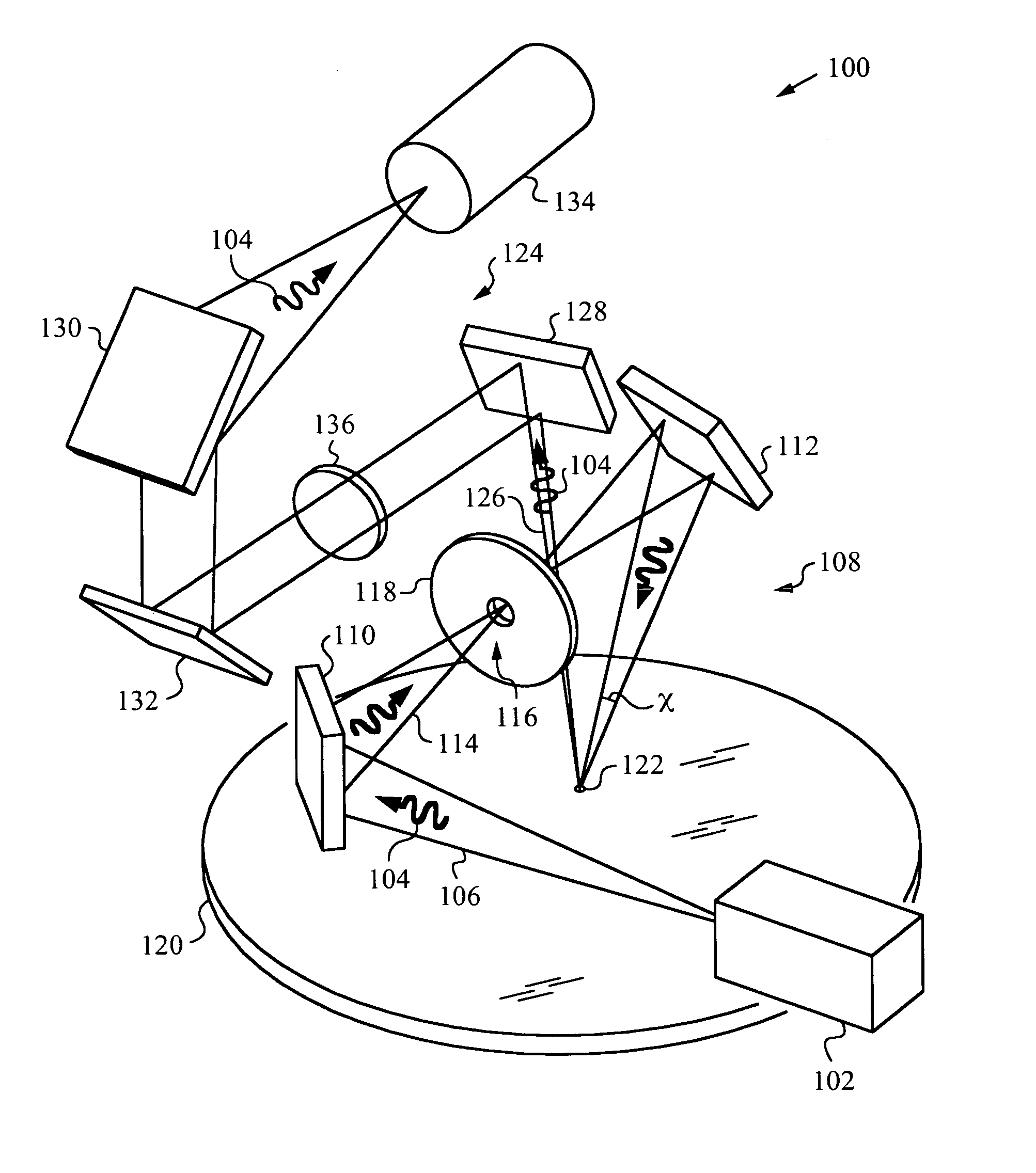
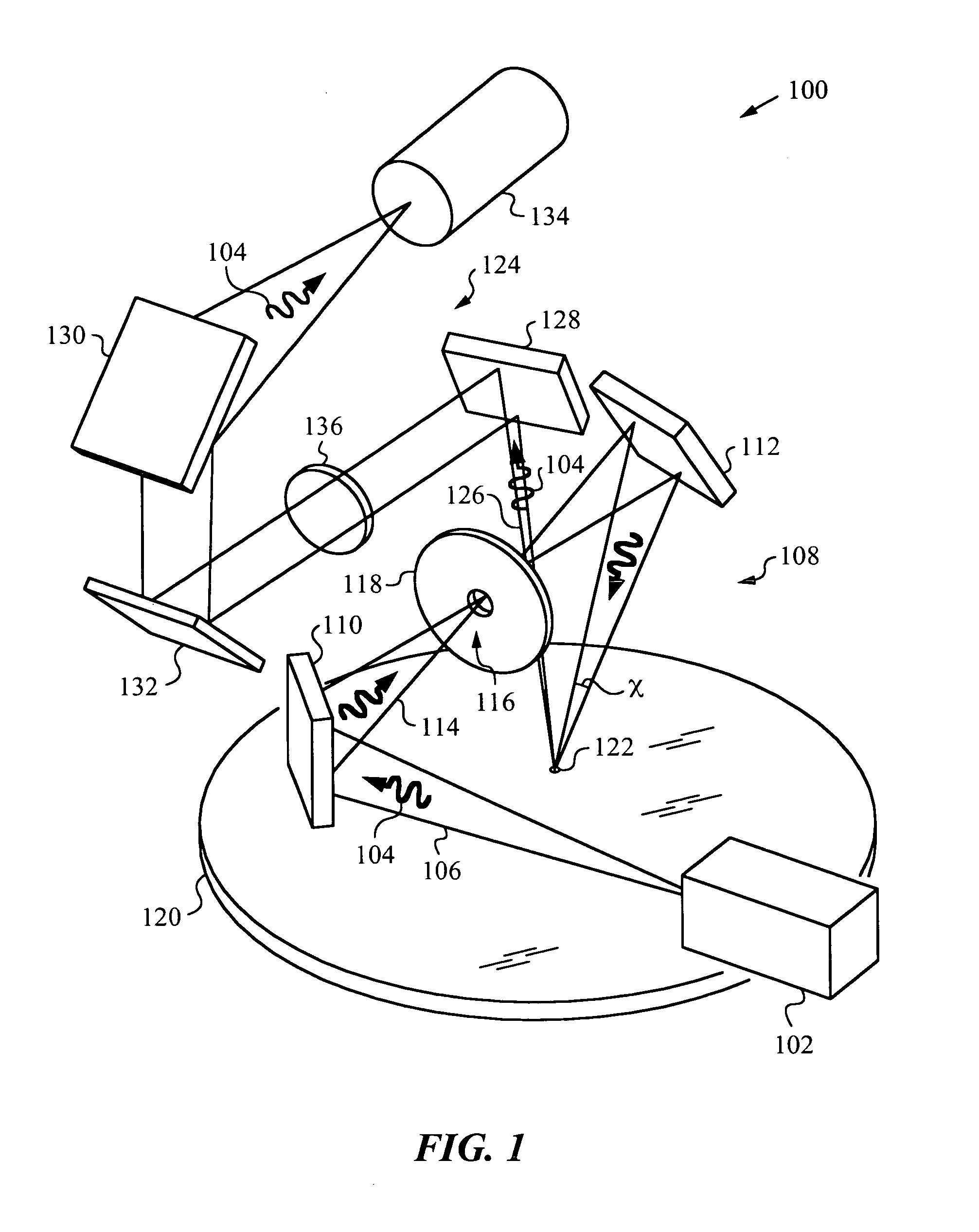
[0057]The isometric view in FIG. 1 illustrates an apparatus 100 for performing optical reflectance metrology in accordance with the principles of the invention. Apparatus 100 has a broadband source 102 for providing broadband radiation 104 spanning a wide spectrum or wavelength range Δλ. Wavelength range Δλ may extend from the deep ultra-violet (DUV), e.g., 190 nm or less, to the far infra-red (IR), e.g., 3,000 nm or more. The type of metrology to be practiced will determine the exact width of wavelength range Δλ. Source 102 can be a compound source that uses two or more individual sources to emit broadband radiation 104 in sub-bands spanning wavelength range Δλ. For example, a visible sub-band of radiation 104 can be generated by a lamp, such as a halogen lamp or a discharge lamp, and an ultra-violet sub-band of radiation 104 can be produced by a DUV deuterium lamp. Additional sources can be used to span the far infra-red part of wavelength range Δλ, as desired. In some embodiments...


PUM


Abstract

Apparatus and method for examining a sample with a broadband radiation while preserving a small spot and low wave front distortion. The apparatus has a broadband source for generating the broadband radiation and a first reflective optics that employ toroidal mirrors that are barrel or donut-shaped and may be placed in a crossed or parallel arrangement for producing a broadband test beam that is guided to the sample such that it is incident on it at a small spot. A sampling aperture is provided for filtering a certain center portion from the broadband test beam. A second reflective optics is provided for shaping a reflected response beam from the broadband radiation that is reflected from the spot. The response beam is delivered by second reflective optics to a detector for examination. The apparatus and method can be applied to improve wave front distortion in reflectance measurements and for performing transmittance measurements with chromatic distortion compensation. The method and apparatus further provide for efficient monitoring of the broadband test beam.

Description

FIELD OF THE INVENTION[0001]This invention relates generally to systems and methods for optical metrology employing broadband radiation, and more specifically to systems and methods that employ broadband metrology using optics that reduce wave front distortion at the examination spot and compensate for chromatic dispersion while also permitting beam monitoring.BACKGROUND ART[0002]There are a number of optical metrology systems and applications including scatterometry, polarimetry, spectroscopy and ellipsometry that require a broadband test beam. The large bandwidth or wavelength range Δλ of the radiation used in these test beams imposes a set of constraints on the optical system and on a number of its operating parameters. The most important constraints are the increasing wave front distortion encountered when employing refractive optics in apparatus for these applications as well as chromatic dispersion.[0003]To limit chromatic dispersion, a number of prior art references teach the...

Claims


Application Information

Patent Timeline
IPC IPC(8): G01B11/14G01J3/02G01J3/42
CPCG01J3/02G01J3/0208G01J3/021G01J3/0229G01N21/8806G01N21/956
Inventor LI, GUOGUANG
Owner N & K TECH
Why Eureka
Try Eureka