Flex spectrum WSS

a technology of flex spectrum and optical network, applied in the field of optical communication system and wavelength division multiplexed optical network, can solve the problems of preventing optimization of key optical parameters of the system, such as passband, and insufficient anamorphic beam expansion created by gratings,

Active Publication Date: 2010-07-13
CAPELLA PHOTONICS INC
View PDF73 Cites 18 Cited by
  • Summary
  • Abstract
  • Description
  • Claims
  • Application Information

AI Technical Summary

Benefits of technology

[0032]Components of the WSS such as the collimator array 102, the port mirror array 106, the beam expander and relay system 110, the beam focusing optics 116, the channel beam deflector arrays 118A, 118B and the array selector 119 may be configured to reduce the detrimental effects of diffraction at the edges of beam deflectors such as micromirrors as described below.
[0111]From the foregoing, it may be seen that reconfigurable optical add-drop systems and methods in accordance with embodiments of the invention afford a simplified and integrated architecture having a number of advantages. Among others, these include the ability to accommodate different channel spacings, effective, flexible and highly accurate methods of power management of individual spectral channels on a channel-by-channel basis; hitless switching of channels that avoids cross-talk and interference to intermediate channels; notchless operation that enables accurate management of power across channels and operation at various wavelength grid spacing; optimization of optical characteristics resulting in high passband and ITU channel alignment; and optimum mechanical characteristics of both the modules and components such as micromirrors.

Problems solved by technology

Therefore, in some wavelength switches that lack control of the beam size expansion before grating diffraction and incident to the focusing optics, results in a spot size on a channel micromirror that is not readily controllable.
Simply accepting the anamorphic beam expansion created by a grating may be insufficient to minimize the spot size on the channel micromirrors to create a wide passband.
In general, these factors prevent optimization of key optical parameters of the system, such as passband, and key mechanical parameters of the micromirrors, such as resonant frequency, which is inversely proportional to the mass of the mirror, and aerodynamic interaction between micromirrors, which is approximately proportional to their length to the third power.
During repositioning, the channel micromirror scans the input spectral channel beam across (i.e., “hits”) intermediate ports, which couples unwanted light into the intermediate ports, and causes crosstalk.
However, this approach has the disadvantage of requiring additional components, including a relay lens system to create a focal plane at the liquid crystal array, the liquid crystal array itself, and electronics to control the liquid crystal array.
In addition to the added costs for such additional components, more physical space is needed to accommodate these components, which increases the overall size and complexity of the system.
A disadvantage of this latter approach is that decoupling the spectral channel beam spatially repositions the beam along the switching axis.
Depending upon the physical spacing of adjacent output ports, a portion of the beam may be cross-coupled into an adjacent output port, causing detrimental cross-talk between the ports.
Increasing the physical spacing of the ports to decrease the cross-coupling undesirably increases the physical size of the device.
Furthermore, as will be described in detail later, using this approach it is difficult to accurately control the power output levels of spectral channels due to the sensitivity of the coupling to rotation of the channel mirror about the switching axis.
While each of the aforementioned patents and embodiments known in the art addresses some of the integrated functionality desired in a wavelength selective switch, they fail to achieve a satisfactory level of integration of the desired functionality, performance, or accuracy of control.
Conventional WSS designs can only handle one channel spacing.

Method used


Image

  • Flex spectrum WSS
  • Flex spectrum WSS
  • Flex spectrum WSS

Examples


Embodiment Construction

[0027]Although the following detailed description contains many specific details for the purposes of illustration, anyone of ordinary skill in the art will appreciate that many variations and alterations to the following details are within the scope of the invention. Accordingly, the embodiments of the invention described below are set forth without any loss of generality to, and without imposing limitations upon, the claimed invention.

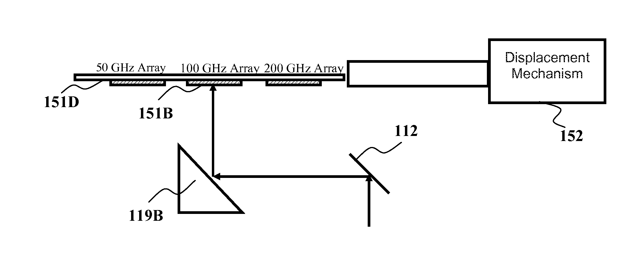
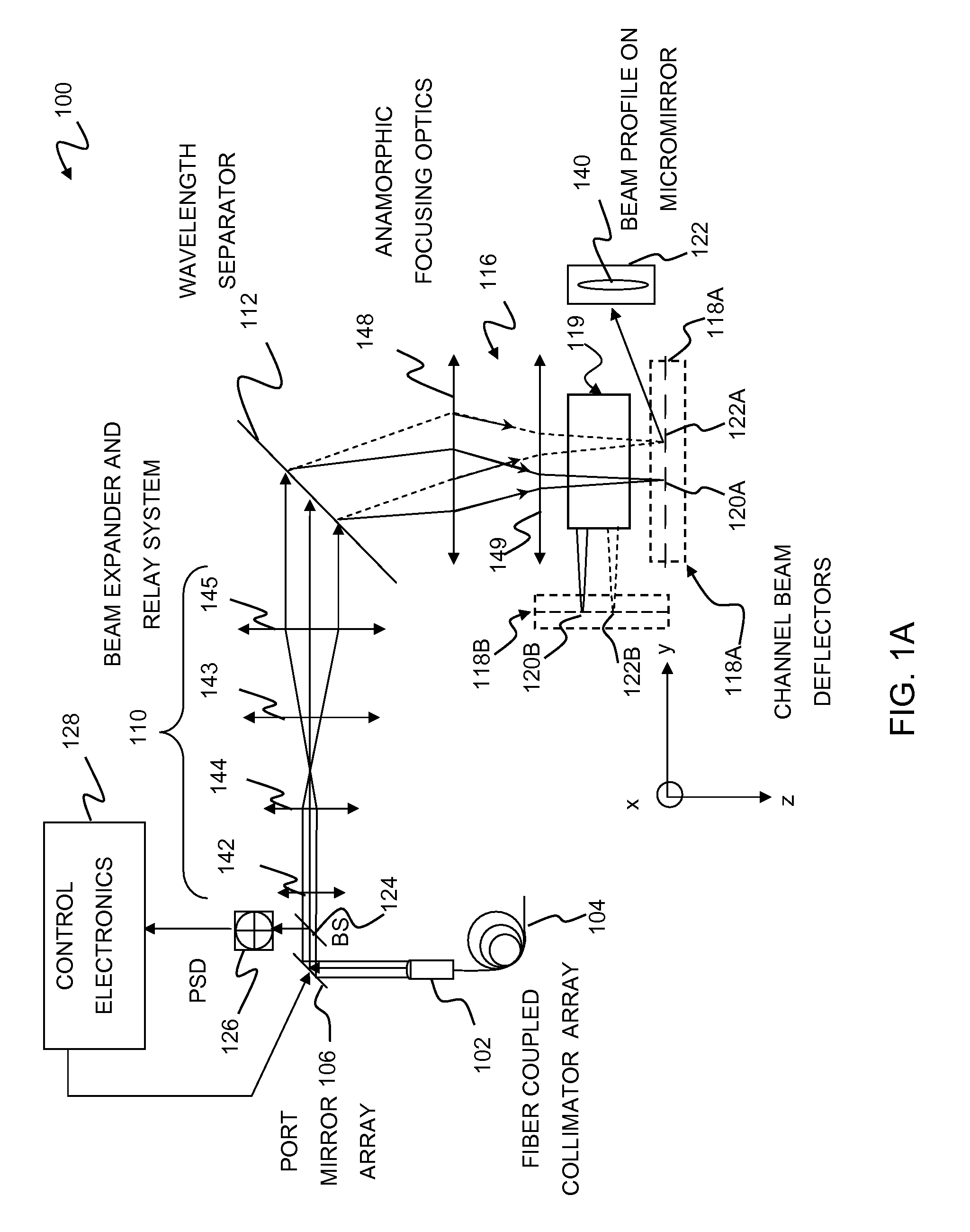
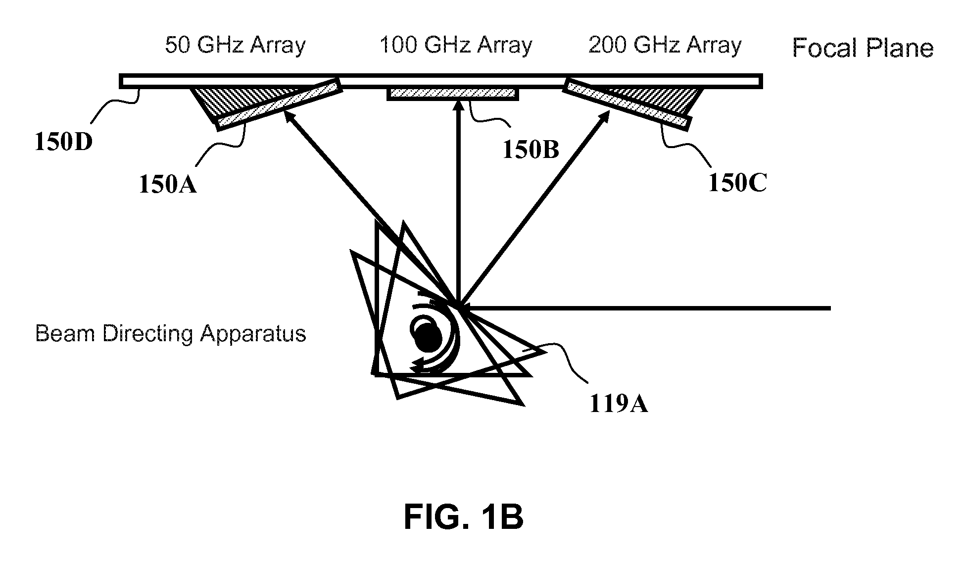
[0028]FIG. 1A is a diagrammatic view that illustrates the architecture of a portion of a wavelength selective switch 100 in accordance with an embodiment of the invention. One or more wavelength selective switches having an architecture as shown in the figure and configured as ADD or DROP modules, may be combined in a ROADM at a node of a wavelength division multiplexed (WDM) optical network, for example. As shown, WSS 100 may comprise a fiber collimator array 102 which provides a plurality of input and output ports for optical signals that are input ...


PUM


Abstract

Switching optical signals containing a plurality of spectral channels characterized by a predetermined channel spacing is described. A selected beam deflector array may be selected from among a plurality of available beam deflector arrays configured to accommodate spectral channels of different channel spacings. The selected beam deflector array is configured to accommodate spectral channels of the predetermined channel spacing. The spectral channels are selectively optically coupled to the selected beam deflector array, which selectively optically couples the spectral channels between one or more input ports and one or more output ports.

Description

CROSS-REFERENCE TO RELATED APPLICATIONS[0001]This application is a continuation in part (CIP) of the application Ser. No. 11 / 103,839, to Joseph E. Davis et al., entitled “Optimized reconfigurable optical add-drop multiplexer architecture with MEMS-based attenuation or power management”, filed on Apr. 11, 2005, now U.S. Pat. No. 7,263,253 the entire disclosures of which are incorporated herein by reference.FIELD OF THE INVENTION[0002]This invention generally relates to optical communications systems and methods for wavelength division multiplexed (WDM) optical networks, and more particularly to wavelength selective switch (WSS) systems and methods that can accommodate different channel spacings in multi-channel optical signals.BACKGROUND OF THE INVENTION[0003]Multi-channel optical signals of the type to which the invention pertains comprise a plurality of spectral channels, each having a distinct center wavelength and an associated bandwidth. The center wavelengths of adjacent channe...

Claims


Application Information

Patent Timeline
Patent Type & Authority Patents(United States)
IPC IPC(8): G02B6/26
CPCG02B6/29311G02B6/29382G02B6/356G02B6/3588G02B6/3594G02B6/4246G02B6/2706G02B6/3512
Inventor GARRETT, MARK H.DAVIS, JOSEPH E.
Owner CAPELLA PHOTONICS INC
Why Eureka
Try Eureka