High pressure gas tank heat management by circulation of the refueling gas

a technology of refueling gas and high pressure, which is applied in the direction of liquid handling, packaging goods, container discharging methods, etc., can solve the problems of limited cooling capacity of the refueling gas as a coolant, and achieve the effects of reducing energy loss, reducing heat loss, and increasing the refueling efficiency of the hydrogen refilling system

Active Publication Date: 2010-07-20
HONDA MOTOR CO LTD
View PDF1 Cites 28 Cited by
  • Summary
  • Abstract
  • Description
  • Claims
  • Application Information

AI Technical Summary

Benefits of technology

[0008]It is an object of the present invention to minimize energy loss and increase refueling efficiency in hydrogen refilling systems when factored into the overall energy efficiency of an infrastructure of high pressure gas powered vehicles and fuel depots for the consumer dispensation of high pressure fuel. Typically, each time a vehicle is refueled with hydrogen, mechanical compression transforms into thermal energy and results in the heating of refueled gas in the tank, hence, it is an object of the invention to minimize tank heating and to increase the efficiency and refueling capacity of an on board fuel storage tank in a hydrogen powered motor vehicle. It is an object of the invention to minimize high pressure gas tank heating and to increase the efficiency and refueling capacity of an on board fuel storage tank in high pressure gas powered motor vehicles. It is an object of the invention to provide a system that can remove the compression heat resulting from refueling an on board tank during high pressure refueling. An avoidance of secondary gas cooling pretreatment and / or pressure overfill, a speedier refueling time, increased refueling efficiency, and an extension of overall vehicle range will result. Improved tank capacity per unit volume is achieved during refilling, particularly where nominal refill pressure is in the range of about 10,000 psi or greater for hydrogen and about 3,600 psi for CNG. It is also an object of the invention to utilize the cooling system in reverse, namely, to provide heat to the gas within the tank as the tank cools during evacuation as the vehicle is operated and the fuel is consumed, resulting in a lowered tank pressure. When the gas is heated, a benefit results that additional gas can be evacuated from the tank, further increasing the range of vehicle operation.SUMMARY OF THE INVENTION
[0009]The invention provides a system that can remove the heat of compression resulting from the high pressure refueling of an on board vehicle tank decreasing refueling time, improving refueling efficiency, and increasing overall vehicle range. In accordance with the present invention, effective reduction of fuel tank heating during the refueling process is provided by introducing the refueling gas into an ejector pump that sucks out the hot gas from within the tank and circulates the hot gas through internal and external heat exchangers to cool the gas. The cooled gas and the refueling gas are mixed in the ejector and then both gas streams are directed into the vehicle storage tank. During vehicle operation, the cooling system is operated in reverse to warm gas in the tank to enhance tank evacuation as well as to maintain the temperature of the seals associated with the tank system warmer than the lower temperature limit of the seals.
[0010]In various embodiments, utilizing the refueling gas as a coolant has a limitation of cooling capacity. Some tanks which have a gas absorbing material such as metal hydride, MOF, carbon nano-tube, etc., release much more heat than the simple high pressure tank during a refueling. It is an object of the invention to improve the heat exchange ability in the refueling gas cooling tank.
[0011]In brief, the invention provides a system for reducing the energy and for reducing the time required to refill on board tanks on a vehicle from a high pressure fuel depot refilling line operatively interconnected to the tank wherein the refilling gas itself is circulated within the on board tank to absorb the compression heat of refueling, and the heat thereby absorbed, is radiated from the cooling circuit to an external environment before the fuel reaches the tank such that a close to optimum refill of the tank is achieved. In the invention, a gas jet ejector or Venturi pump utilizes the energy in the high pressure gas to create a lower pressure that can entrain another gas stream and provide a continuous circulation loop for greater cooling of the gas.

Problems solved by technology

In various embodiments, utilizing the refueling gas as a coolant has a limitation of cooling capacity.

Method used


Image

  • High pressure gas tank heat management by circulation of the refueling gas
  • High pressure gas tank heat management by circulation of the refueling gas
  • High pressure gas tank heat management by circulation of the refueling gas

Examples


Embodiment Construction

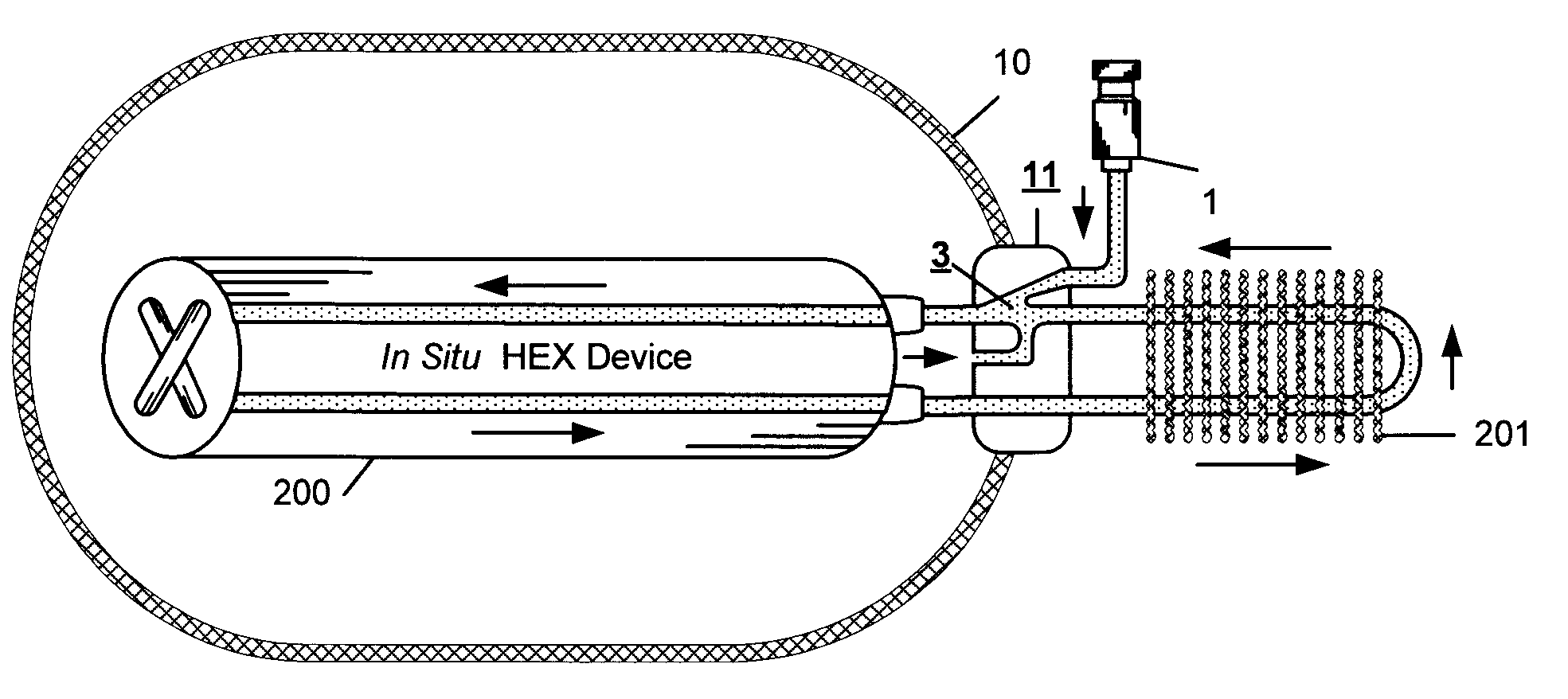
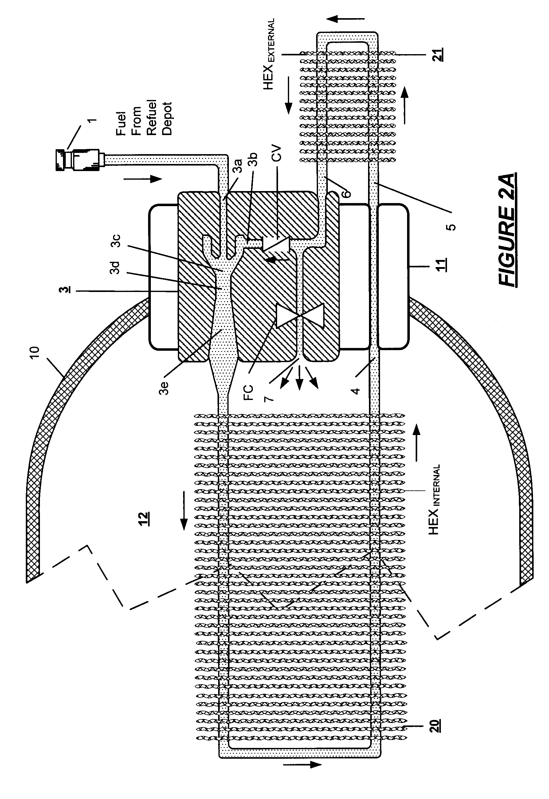
[0019]Utilizing an ejector pump and flow control system, the invention increases the refueling energy efficiency of hydrogen powered vehicles by withdrawing the heat of refilling compression from the high pressure gas introduced into on board tanks. The circulating refueling gas is introduced into an ejector pump that circulates the hot gas in a loop through a heat exchanger where the gas is cooled down and a circulation cycle repeated. Afterwards, the cooler gas and the refueling gas are mixed in the ejector and then a portion of the gas flow, as so cooled, is introduced into the storage tank. During driving, the gas in the fuel tank is warmed by circulation through the external and internal heat exchangers.

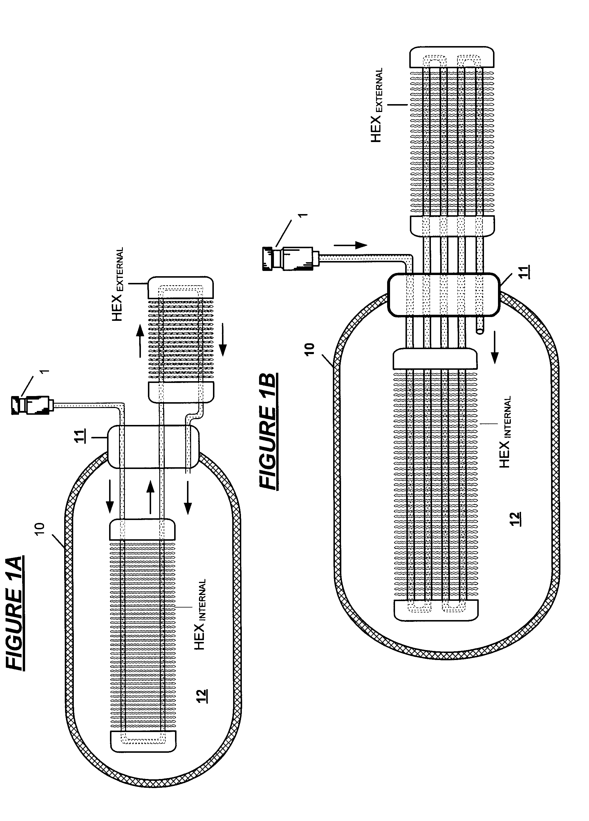
[0020]With reference to FIG. 1A showing a principle of cooling by gas circulation, tank 10 includes interior storage volume 12 and end boss 11 that includes gas flow conduits therethrough for entry of the refill gas from refill receptacle 1 through HEXINTERNAL where heat is abso...


PUM

PropertyMeasurementUnit
pressuresaaaaaaaaaa
pressuresaaaaaaaaaa
pressuresaaaaaaaaaa

Abstract

A heat management system for a high pressure gas tank comprising a loop circulation path for the gas including a path through an internal heat exchanger in the tank and a path through a heat exchanger external to the tank, wherein, in the instance of refueling, the refueling gas circulates multiple times in the loop through the internal heat exchanger and the external heat exchanger and in the course of circulation, a portion of the gas from the refuel line is introduced into the tank. In a reverse circulation during driving, the tank is warmed by heat exchange from the external heat exchanger to the internal heat exchanger.

Description

RELATED APPLICATIONS[0001]This application is a continuation in part of my co-pending applications for United States Letters Patent High Pressure Gas Tank Cooling by Ejector Pump Circulation, Ser. No. 11 / 682,574 filed on Mar. 6, 2007 and Gas Flow Management Equipment for High Pressure Gas Storage Tanks Ser. No. 11 / 682,470 filed on Mar. 6, 2007.FIELD OF THE INVENTION[0002]The present invention relates to a system for efficiently cooling high pressure refill gas that is to be stored in fuel tanks, typically, hydrogen gas and compressed natural gas introduced to the tank at a refueling station. Onboard high pressure tank cooling is effected by circulation of the refill gas using a Venturi or ejector pump.BACKGROUND OF THE INVENTION[0003]Typically, in motor vehicles using hydrogen to power fuel cells or using hydrogen and compressed natural gas (CNG) to power internal combustion engines, present practice is that fuel is stored in on board tanks maintained at a maximum pressure in the ra...

Claims


Application Information

Patent Timeline
Patent Type & Authority Patents(United States)
IPC IPC(8): B65B1/04
CPCF17C13/12F17C2221/012F17C2221/033F17C2260/011F17C2260/021F17C2270/0168Y02E60/321Y02E60/324Y02E60/32
Inventor HANDA, KIYOSHI
Owner HONDA MOTOR CO LTD
Why Eureka
Try Eureka