Wind turbine assembly

a technology of wind turbines and components, applied in the direction of wind turbines with perpendicular air flow, circumferential flow pumps, wind energy generation, etc., can solve the problems of affecting the movement of birds, so as to reduce the exposure of turbine blades, prevent physical overload of generators or drive shafts, and uniform rotation

Inactive Publication Date: 2010-07-20
JARECKI FR
View PDF10 Cites 20 Cited by
  • Summary
  • Abstract
  • Description
  • Claims
  • Application Information

AI Technical Summary

Benefits of technology

[0019]As previously mentioned, the turbine assembly will be sized to produce the needed power output to drive a generator, for example, under average wind conditions with the shutters 50% open. If wind velocity ebbs, the shutters can be opened wider to expose a greater length of each turbine blade. Conversely, when the wind velocity increases above the nominal average value, the shutters can be closed to reduce the turbine blade exposure. This control of rotational speed is needed to provide a substantially uniform rate of rotation. With a DC generator, this is needed to prevent physical overload of the generator or drive shafts. For an AC system, it is typical to operate at a constant alternator speed which will be accomplished by the use of variable speed motors in conjunction with the shutter system of the present invention. By managing turbine blade exposure using the shutter system of the present invention, the need for auxiliary equipment to turn the blades into the wind (as is the case for some prior art systems), is obviated. An alternative means of operating the shutters is to fully open them when the turbine blades are exposed to positive wind force and to fully close the shutters which would expose turbine blades to negative wind force. Obviously, this eliminates some of the control available with the preferred method. The ability of the shutters to fully close affords the turbine assembly the capability to shield the moving parts from gale force winds and other potential weather related damage.
[0020]Second, each of the turbine blades themselves pivot along their inner edge to provide maximum blade exposure to catch the wind on the upstream side of the device and to minimize the resistance to desired rotation by pivoting out of the way on the downstream side of the device. This maximizes the efficiency turbine assembly in converting the potential energy of the wind into useful power.
[0021]The wind turbine assembly of the present invention has a defined footprint of significantly smaller dimension than the propeller blade design currently being used. This affords it the opportunity to be mounted on high rise buildings, cruise ships, and offshore oil platforms, to name several applications for which the prior art systems are incapable of addressing. In addition, as depicted in one of the embodiments of the present invention, two or more turbine assemblies can be mounted on a single columnar supporting structure to enhance the use of space in any of these applications or on a “wind farm”.

Problems solved by technology

With the rising costs associated with finding, extracting and processing petroleum resources, and the ecological impact of utilizing such fuels (both real and imagined), the world is turning to alternative sources of energy.
The wind-powered generators of the existing prior art tend to be large, bulky propeller-like apparatuses that of necessity must be pointed into the wind to function.
In addition to being unsightly, inefficient usages of space, these propeller-like devices are a huge hazard to migratory birds.
Because they slice such a huge swath through the air, unsuspecting flocks flying through / around a wind farm sporting a plurality of such devices lose a significant percentage of birds, cut down in the prime of their lives.
Obviously, this eliminates some of the control available with the preferred method.

Method used


Image

  • Wind turbine assembly
  • Wind turbine assembly
  • Wind turbine assembly

Examples


first embodiment

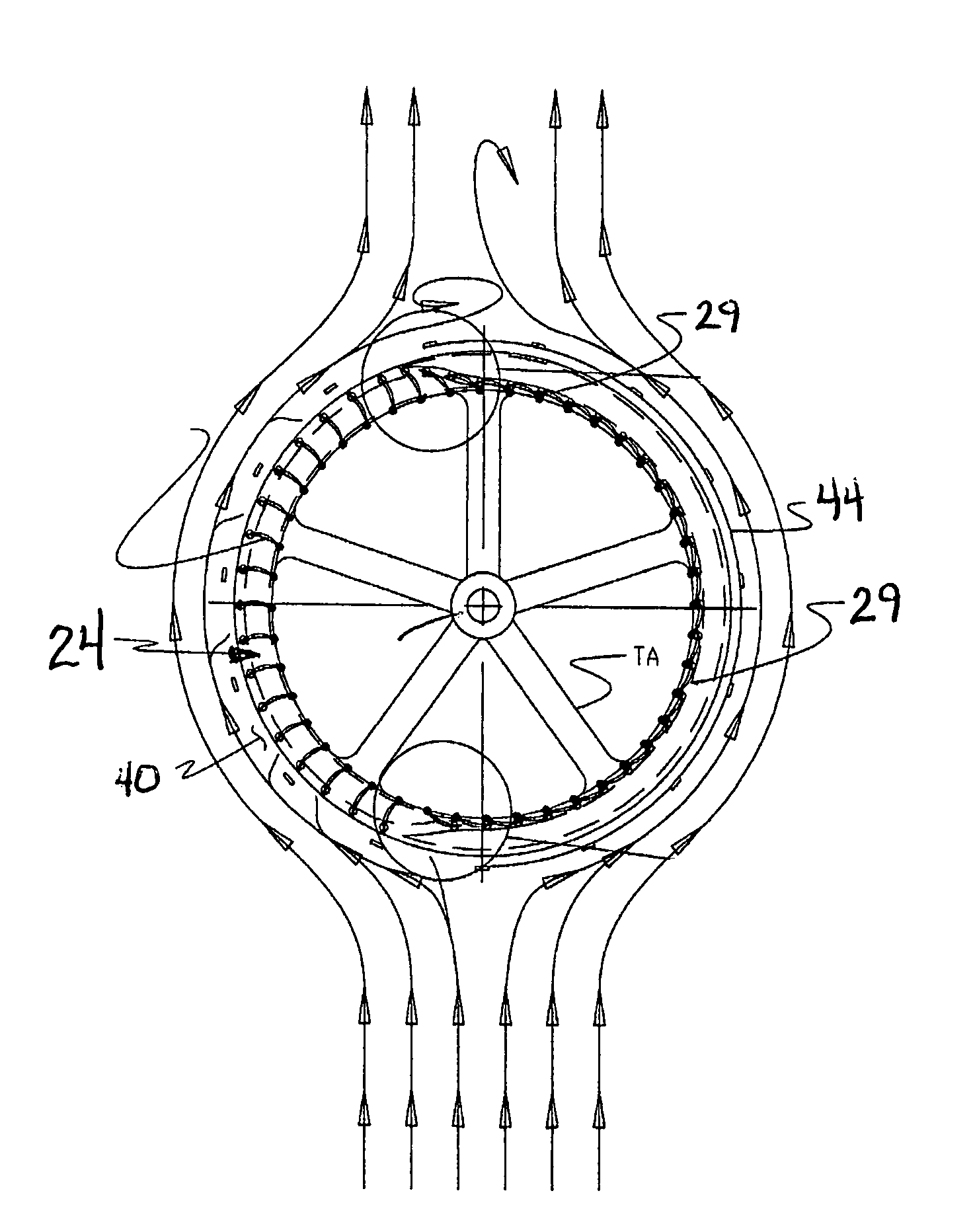
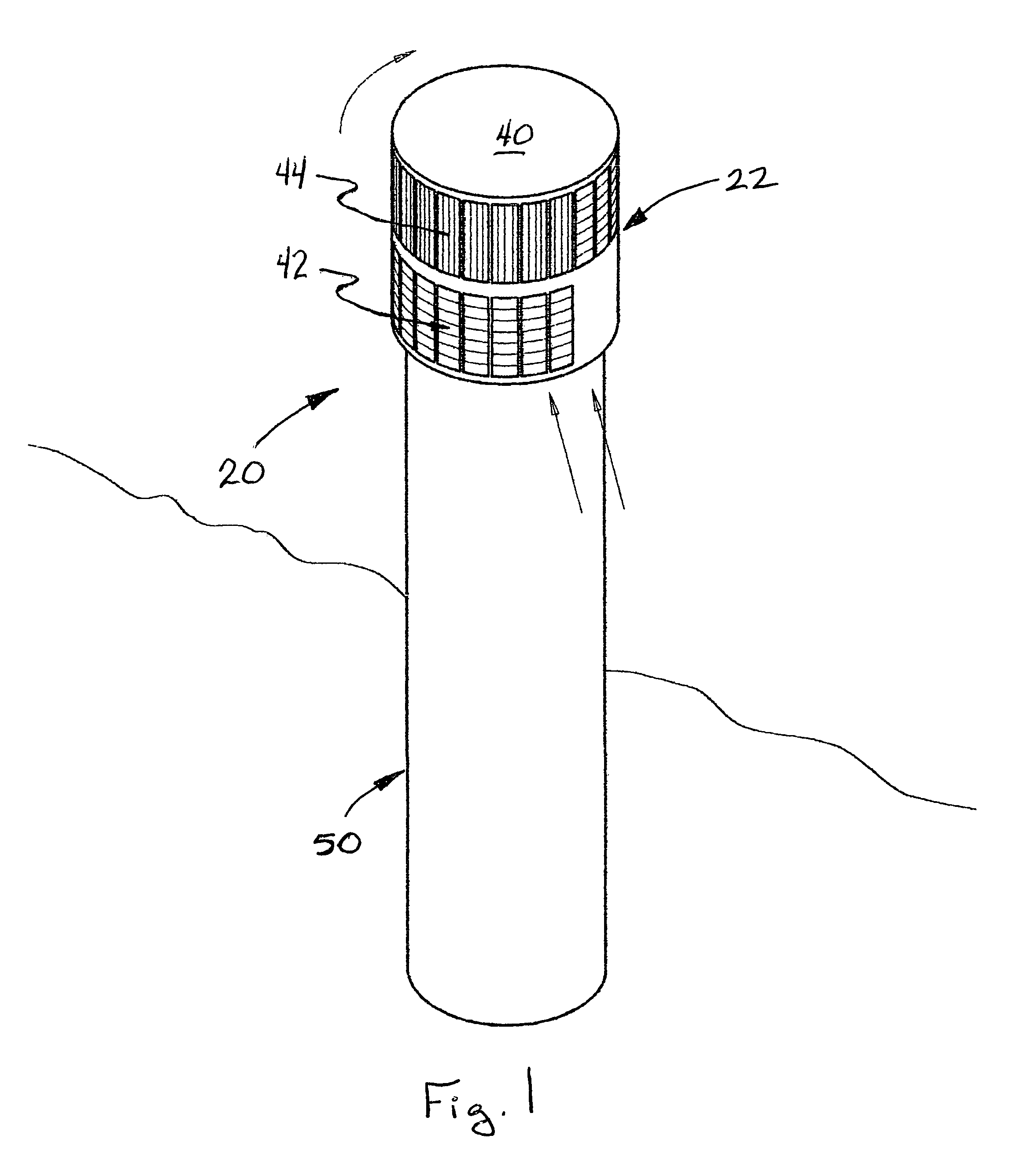
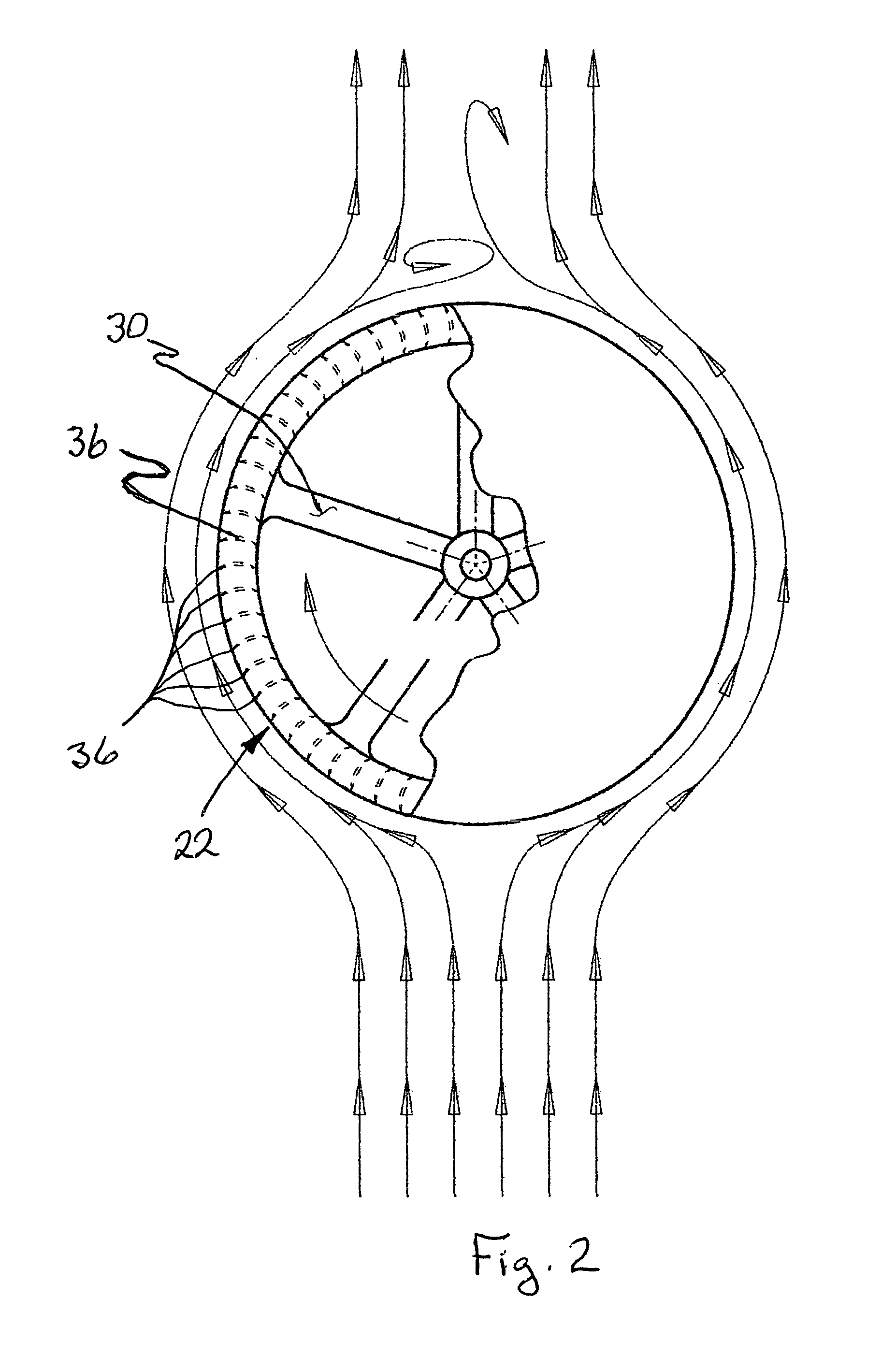
[0043]the wind turbine generator of the present invention is depicted in FIG. 1 generally at 20. Turbine generator 20 consists of a turbine assembly 22 having a first “footprint” with respect to ground coverage. Turbine assembly 22 is mounted on a support tower 50 which has a second footprint that is only slightly smaller than the first. This distinguishes turbine generator 20 from prior art propeller blade wind turbines whose footprint is dozens of times larger than the footprint of its tower. Turbine assembly 22 preferably rotates around a vertical axis making it significantly more “bird friendly” in that there is no downward chopping movement which catches avians unaware. Turbine assembly 22, as best seen in FIGS. 2-3A, 3B, 7, 7A and 7B, comprises a cylindrical drum 24 which has a first upper ring 26 on one end and second lower ring 28 at an opposite end of drum 24. A plurality of spokes 30 extend outwardly from central hub 32 to first ring 26. Hub 32 is connected via shaft 34 to...

second embodiment

[0045]The turbine configuration may be of the open variety as shown in FIGS. 2, 5 or, alternatively, as shown in a second embodiment depicted in FIG. 4, the turbine may be of a closed configuration; that is, an inner housing 45′ can be provided extending between rings 26′, 28′ to prevent wind from passing through the drum 24′. It is believed that the housing 45′, while adding some additional weight, will make up for it by focusing the force of the wind on blades 36′, rather than allowing some of the wind to slip off the surface of blades 36′ into the interior of drum 24′.

[0046]FIG. 9 shows multiple turbines in multiple housings 40A″, 40W′ mounted on a single tower 50″. While only two are shown, obviously, additional turbines could be utilized. Tower 50″ will be sized to position turbine assemblies 22 above buildings, trees, etc., that will interfere with air flow causing wind shear and reducing the effectiveness of the wind turbines.

[0047]FIGS. 10a and 10b depict an alternative conf...


PUM


Abstract

A wind turbine for generating electricity is configured as a drum with a housing that has adjustable shutters to control the amount of wind reaching the turbine blades. Alternatively, the turbine blades can be pivotably mounted and opened and closed using a cam follower, cam track system to minimize wind exposure to downstream turbine blades.

Description

[0001]This application claims the benefit of priority of Provisional Patent Appl. No. 60 / 854,010 filed Oct. 24, 2006.BACKGROUND AND SUMMARY OF THE INVENTION[0002]With the rising costs associated with finding, extracting and processing petroleum resources, and the ecological impact of utilizing such fuels (both real and imagined), the world is turning to alternative sources of energy. One particularly attractive source is wind. Wind is clean, economical, renewable / non-expendable and virtually available everywhere, albeit more routinely accessible in some regions than in others.[0003]The wind-powered generators of the existing prior art tend to be large, bulky propeller-like apparatuses that of necessity must be pointed into the wind to function. This requires that a significant “footprint” be allotted to each generator, exceeding 250 feet in diameter, in some instances, as the blade rotates about its pedestal to catch the wind. In addition to being unsightly, inefficient usages of sp...

Claims


Application Information

Patent Timeline
Patent Type & Authority Patents(United States)
IPC IPC(8): F03D3/04
CPCF03D3/0418F03D3/068Y02B10/30Y02E10/74F03D9/25F03D13/20Y02E10/728
Inventor JARECKI, FRANK
Owner JARECKI FR
Why Eureka
Try Eureka