Methods and apparatus for cryo-therapy

a cryo-treatment and apparatus technology, applied in the field of cryo-therapy, can solve the problems of affecting the efficiency of cryo-treatment devices, affecting the efficiency of cryo-treatment, and inflamed plaques are particularly unstable and vulnerable to disruption, so as to reduce the heat transfer area of guidewires, optimize the efficiency of cooling during treatment, and minimize the exposure of guidewires

Active Publication Date: 2010-07-20
ARRINEX INC
View PDF62 Cites 38 Cited by
  • Summary
  • Abstract
  • Description
  • Claims
  • Application Information

AI Technical Summary

Benefits of technology

[0018]To minimize the exposure of the guidewire to blood, fluids, or other tissue, insulative barriers or shingles may be attached to at least a portion of the loops to help insulate the guidewire. Reducing the heat transfer area of the guidewire to tissue or blood not being treated may aid in optimizing the efficiency of the coolant during treatment.

Problems solved by technology

Plaque that is inflamed is particularly unstable and vulnerable to disruption, with potentially devastating consequences.
However, problems exist with conventional cooling and cryo-treatment devices.
One such problem is that conventional devices usually exert an undue amount of force on the region of interest.
If the region of interest cannot withstand these forces, it may be damaged.
The inside walls of a healthy human artery are vulnerable to such damage.
Furthermore, if inflamed, unstable plaque is present it may be ruptured by such forces.
Another problem with conventional devices is that they can only treat tissue at one specific location.
This can be very tedious, can increase the risk of damaging the vessel wall or rupturing vulnerable plaque, and may not treat the entire region of tissue.

Method used


Image

  • Methods and apparatus for cryo-therapy
  • Methods and apparatus for cryo-therapy
  • Methods and apparatus for cryo-therapy

Examples


Embodiment Construction

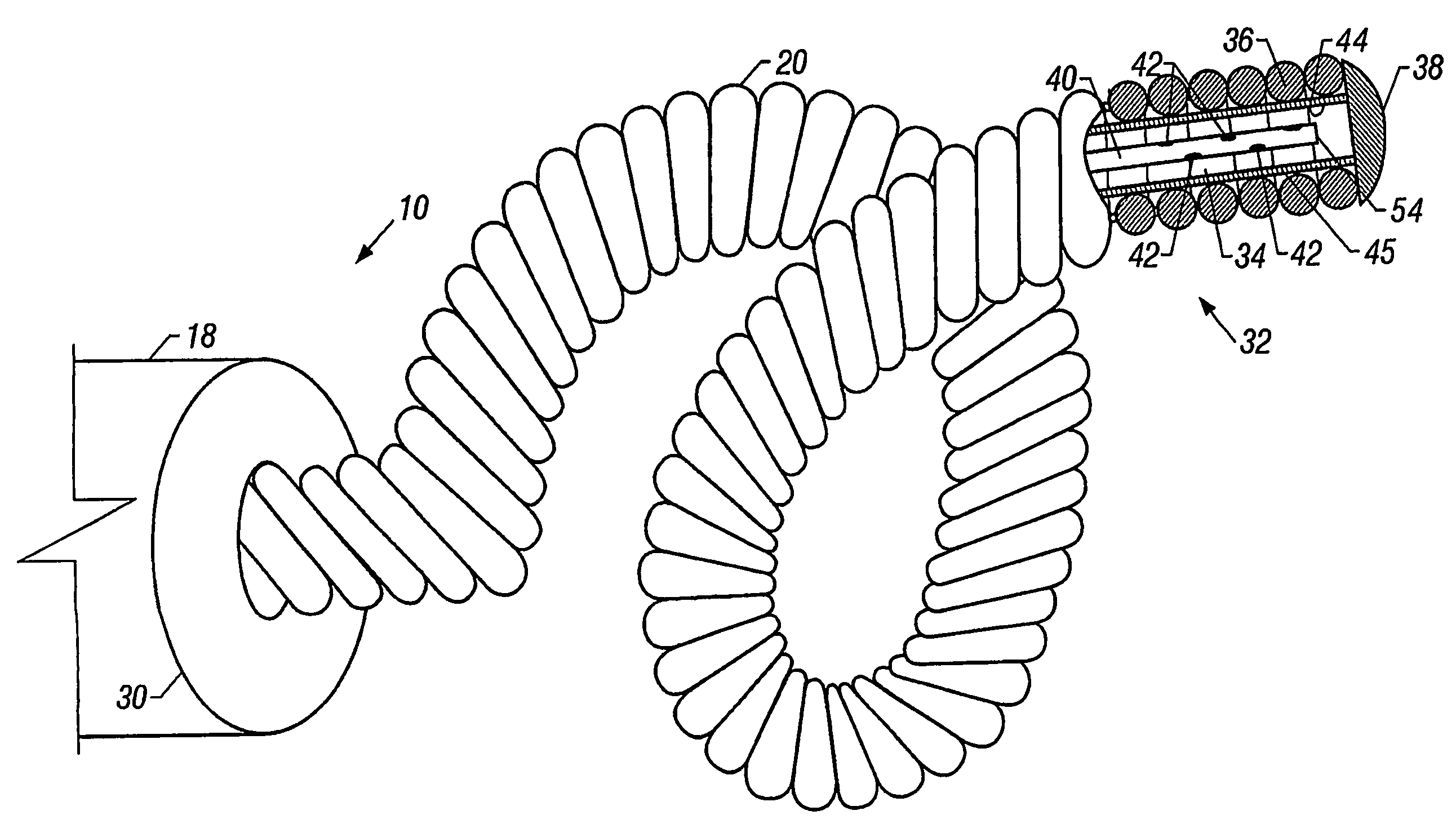
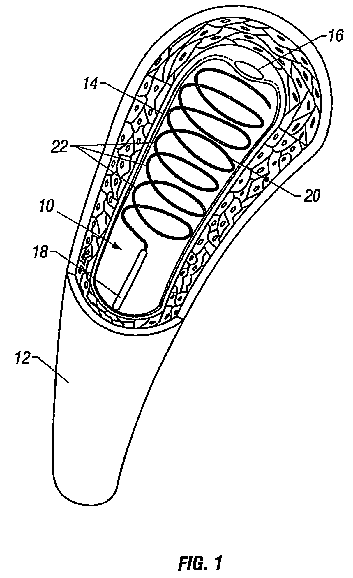
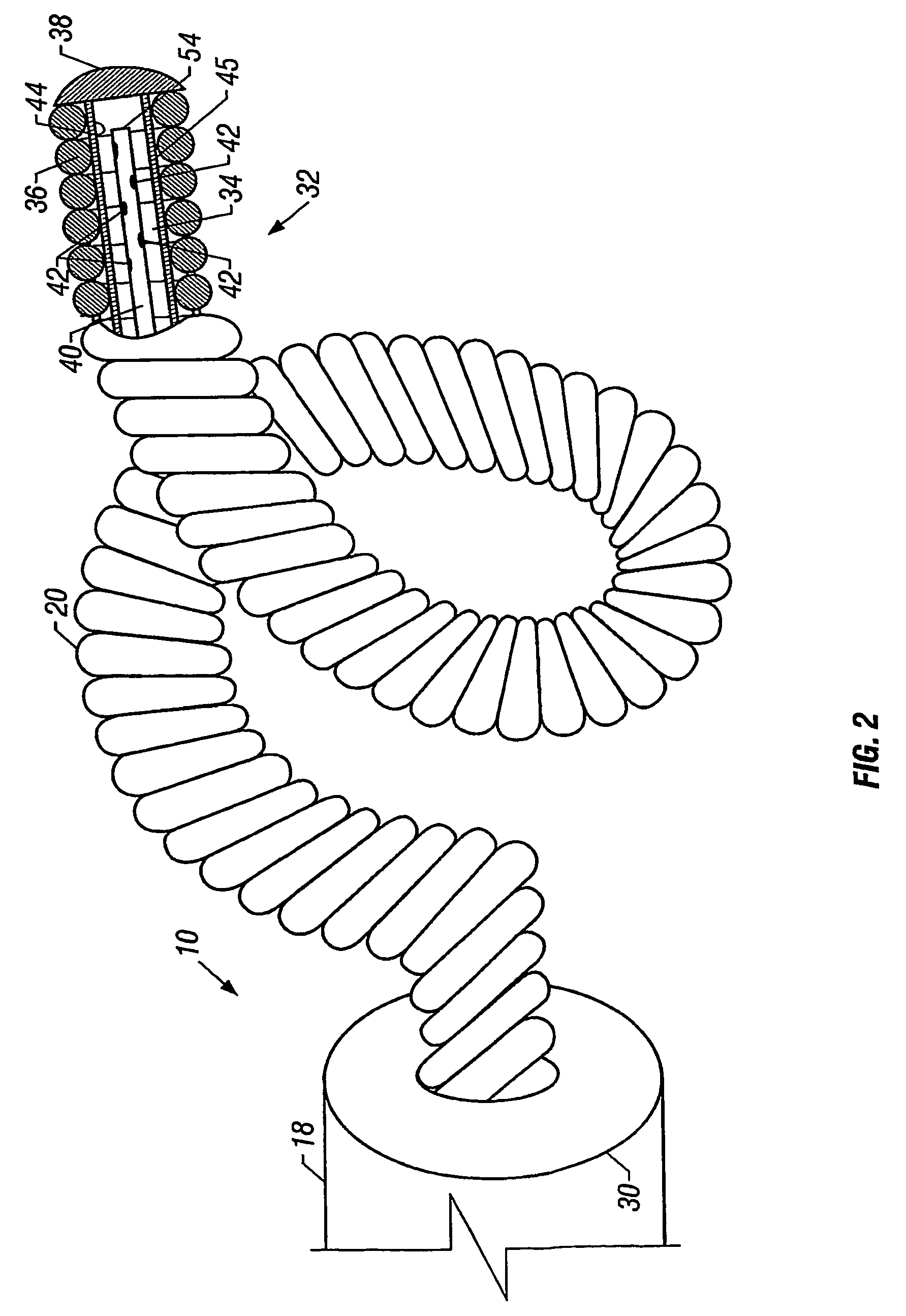
[0043]Cryogenic treatment of tissue may involve many different device variations and methods. As shown in FIG. 1, cryo-therapy device 10 is shown positioned within arterial blood vessel 12, which has its wall partially removed for clarity. One variation of the device 10 is shown as having a hollow guidewire 20 configured to form multiple loosely spaced helical loops 22. Guidewire 20 is preferably made of a thin wire which may be wound into small helical coils of a predetermined diameter that may lie tightly adjacent to one another to form a hollow guidewire 20 defining a central passageway. These loops 22 may be held within lumened catheter 18 in a first configuration while being delivered to the desired treatment site.

[0044]Once ejected or pushed from catheter 18, guidewire 20 may be self-deploying or self-forming such that when it is unconstrained, it reconfigures itself into a second configuration. This may be accomplished by having guidewire 20 self-form or spring into helical l...


PUM


Abstract

Methods and apparatus for cryo-therapy are disclosed herein. This includes a hollow guidewire disposed within a catheter having helical loops contacting tissue. A coolant delivery tube disposed within can have a coolant delivered from a proximal end into the guidewire lumen. The coolant flows back proximally through the guidewire while cooling the guidewire surface and cooling or cryogenically ablating the contacting tissue. To minimize guidewire exposure to surrounding fluids or tissue, insulative barriers can be attached to the guidewire. A coolant delivery tube and return lumen can be integrated from a single extrusion in various configurations. Expandable balloons can also be used to expand the loops of the guidewire to contact the tissue. Also, helical loops with a coolant delivery tube or stem disposed longitudinally within the loops can be used and the loops can also have a variable collapsible cooling region.

Description

CROSS-REFERENCE TO RELATED APPLICATIONS[0001]This application claims the benefit of U.S. Provisional Patent Application No. 60 / 350,177, entitled “Methods and Apparatus for Cryo-Therapy” filed Nov. 2, 2001, and U.S. patent application Ser. No. 10 / 010,399, entitled “Methods and Apparatus for Cryo-Therapy” filed Dec. 5, 2001, now abandoned.TECHNICAL FIELD OF THE INVENTION[0002]The present invention relates to cryo-therapy. More particularly, the present invention relates to methods and apparatus for endovascularly cooling and / or freezing preselected regions of tissue.BACKGROUND ART OF THE INVENTION[0003]Acute ischemic syndromes involving arterial blood vessels, such as myocardial infarction, or heart attack, and stroke, frequently occur when atherosclerotic plaque ruptures, triggering the formation of blood clots, or thrombosis. Plaque that is inflamed is particularly unstable and vulnerable to disruption, with potentially devastating consequences. Therefore, there is a strong need to ...

Claims


Application Information

Patent Timeline
Patent Type & Authority Patents(United States)
IPC IPC(8): A61B18/02A61F7/12A61B17/00A61B17/22A61B18/00
CPCA61B18/02A61B2017/00292A61B2017/00867A61B2017/22001A61B2017/22038A61B2017/22051A61B2018/00101A61B2018/0022A61B2018/0212A61B2018/0262
Inventor SAADAT, VAHID
Owner ARRINEX INC
Why Eureka
Try Eureka