
Apparatus and method for stabilizing image sensor black level

a technology of image sensor and black level, applied in the field of electromechanical imaging sensors, can solve the problems of reducing image quality, affecting image quality, and double the concomitant video bandwidth, so as to maximize the dynamic range in the analog domain, improve image quality, and improve image quality.

Active Publication Date: 2010-07-20
SAMSUNG ELECTRONICS CO LTD
View PDF15 Cites 36 Cited by
  • Summary
  • Abstract
  • Description
  • Claims
  • Application Information

AI Technical Summary

Benefits of technology

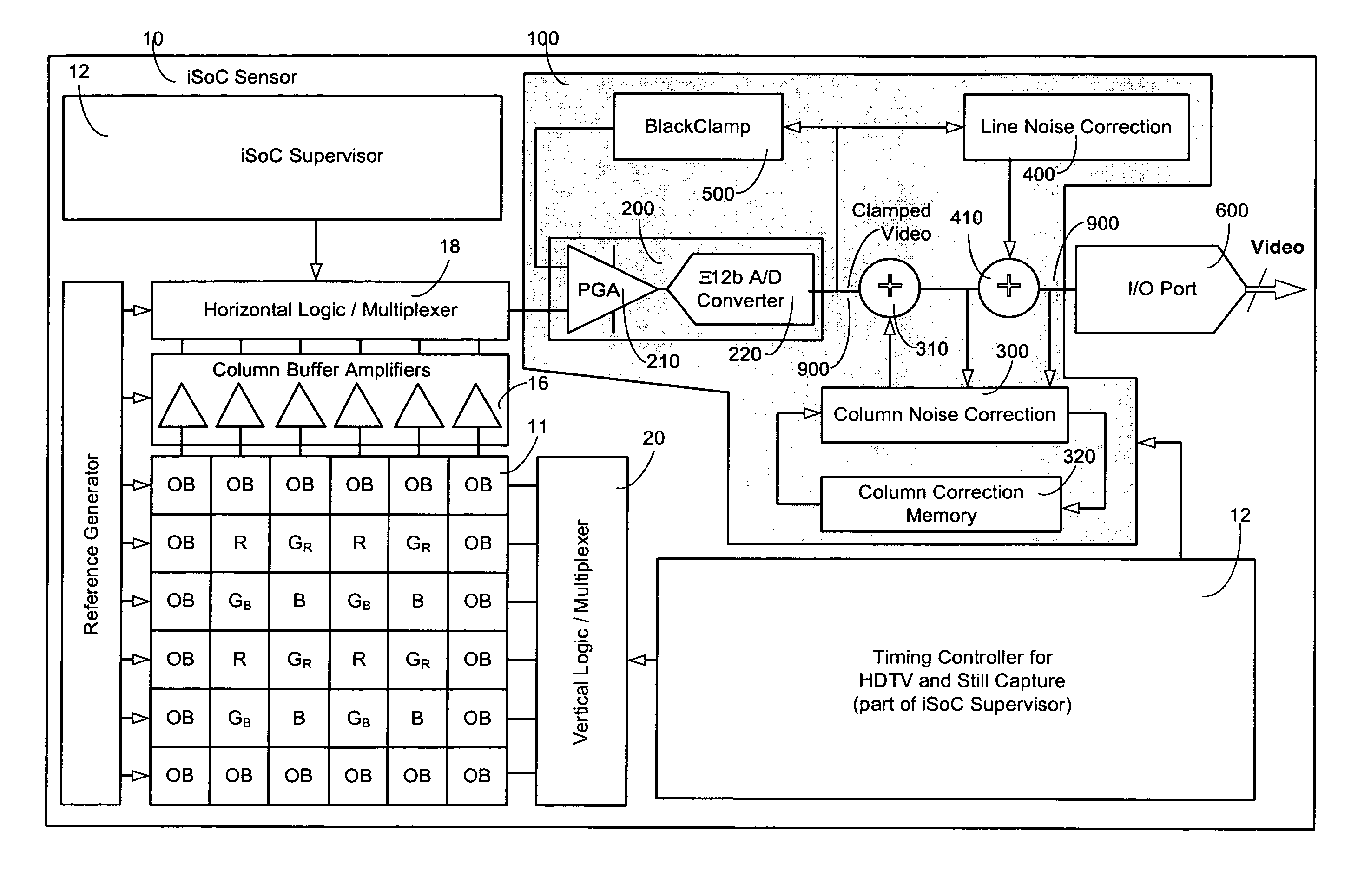
[0014]The present invention includes a method, circuit implementation and firmware code that together provide superior black level stabilization. Analog circuits, digital circuits, and algorithms jointly suppress the various fixed pattern noise sources inherent in “reading out” arrays of image-sensing pixels, while simultaneously maximizing the dynamic range in the analog domain. In a preferred embodiment, the noise suppression is performed in the digital domain using algorithms specifically optimized to produce electronic images with useful image quality spanning at least 16 bits of dynamic range, even though only 12 bits may be supplied to the camera from frame-to-frame.

Problems solved by technology

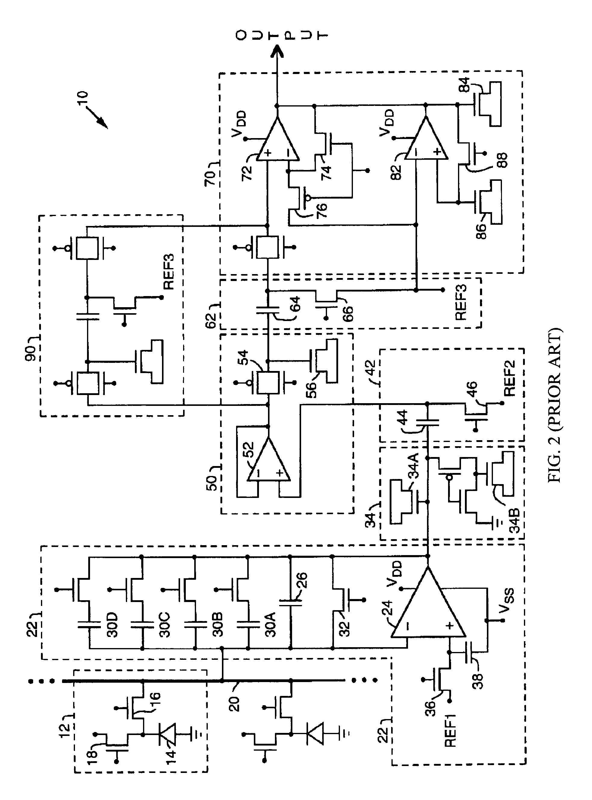
Although modem CMOS sensors have lower temporal noise than CCD imaging sensors at data rate >25 MHz, several sources of systematic artifacts can degrade image quality, especially at low illumination.
In high performance imaging sensors, the most distracting effect is frame-to-frame instability.
Unfortunately, burdening the signal path by also supplying the reset level to the offset-subtracting amplifier halves the maximum video rate, doubles the concomitant video bandwidth, and boosts white noise.
The correction is also carried out at high speed on a pixel-by-pixel and per-color basis, thus increasing complexity and signal processing overhead.
This effectively limits accuracy of the various corrections rather than enhancing the analog dynamic range presented for A / D conversion.

Method used


Image

  • Apparatus and method for stabilizing image sensor black level
  • Apparatus and method for stabilizing image sensor black level
  • Apparatus and method for stabilizing image sensor black level

Examples


Embodiment Construction

[0063]The following description is provided to enable any person skilled in the art to make and use the invention and sets forth the best modes contemplated by the inventor for carrying out the invention. Various modifications, however, will remain readily apparent to those skilled in the art. Any and all such modifications, equivalents and alternatives are intended to fall within the spirit and scope of the present invention.

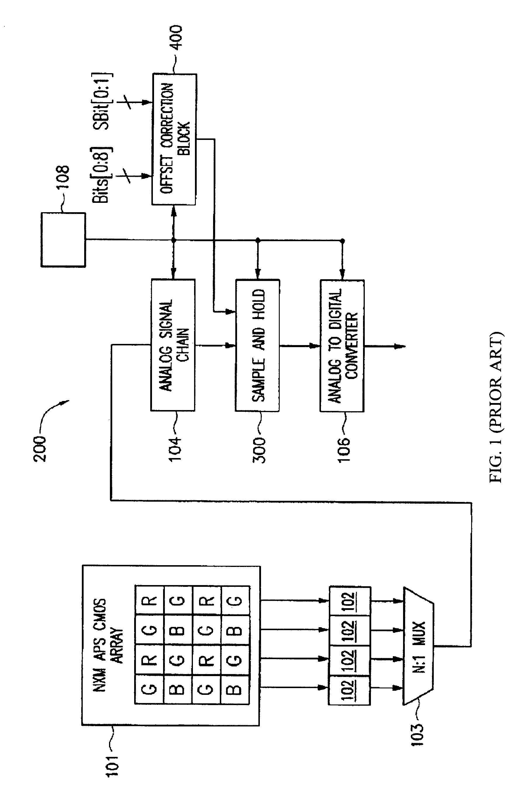
[0064]In general, conventional image sensors consist of a pixel array that outputs an image signal, and digital imaging processing blocks that are designed to increase the quality of the resulting image. Currently, there are three general types of processing algorithms used: black clamping, line noise correction, and column fixed pattern noise (FPN) correction. Historically, these algorithms have been deployed in a separate and discrete fashion, with each algorithm operating independently of the others (see FIG. 3). The present invention, however, as described ...


PUM


Abstract

A black clamp stabilization circuit for an image sensor utilizes a mixed-signal SoC block comprising sub-blocks to dynamically and precisely adjust the black level based on comparison to a reference black level. The black level adjustments include a first level regulation using digital control of an analog signal in a feedback loop that includes a programmable gain amplifier and high-resolution A / D converter. By applying the black clamping in the analog domain, dynamic range is extended. Additional black level regulation is subsequently performed in the digital domain to differentially eliminate line noise and column noise generated within the imaging System-on-Chip. By providing information between the sub-blocks, the algorithms can converge more quickly. The technique enables multiple signal paths to separately handle individual colors and to increase imaging data throughput.

Description

COPYRIGHT NOTICE[0001]A portion of the disclosure of this patent document contains material which is subject to copyright protection. The copyright owner has no objection to the facsimile reproduction by anyone of the patent document or the patent disclosure, as it appears in the Patent and Trademark Office patent file or records, but otherwise reserves all copyright rights whatsoever.CROSS-REFERENCE TO RELATED APPLICATIONS[0002]The present invention is related to: U.S. patent application Ser. No. 11 / 715,798, entitled, “CROSS-COUPLED DIFFERENTIAL DAC-BASED CLAMP CIRCUIT,” filed Mar. 7, 2007, the disclosure of which is herein incorporated by reference.BACKGROUND OF THE INVENTION[0003]1. Field of the Invention[0004]The present invention relates generally to electronic imaging sensors and, specifically, to advanced imaging system-on-chip (iSoC) sensors having embedded signal processing functions.[0005]2. Description of the Related Art[0006]Imaging sensors operate by collecting light in...

Claims


Application Information

Patent Timeline
Patent Type & Authority Patents(United States)
IPC IPC(8): H04N5/335H04N5/217H04N25/00
CPCH04N5/2176H04N5/361H04N5/3658H04N25/677H04N25/633H04N25/673H04N25/618H04N25/63
Inventor HUANG, YINGROSSI, GIUSEPPEMARCHESINI, ROBERTOMAO, QIANJIANG BOBWALLNER, JOHNRICHARDSON, JOHNBLANQUART, LAURENTSHAH, JOEY
Owner SAMSUNG ELECTRONICS CO LTD
Learn More