Conservation tillage implement, system and method

a technology of tillage implements and implements, applied in the field of tillage implements and crop residue management, can solve the problems of residues preventing soil, delay in planting crops, and falling out of favor of conventional tillage practices, so as to reduce inventory costs and delivery time, reduce farmer's expense, and save costs

Active Publication Date: 2010-07-27
SALFORD GRP INC
View PDF33 Cites 26 Cited by
  • Summary
  • Abstract
  • Description
  • Claims
  • Application Information

AI Technical Summary

Benefits of technology

[0018]The use of individual coulter wheel assemblies provides several advantages as compared with gang-shaft mounted coulter wheels. Maintenance is simplified, as the individual coulter wheel assemblies may be readily replaced without removal of the entire gang shaft. Individual coulter wheel assemblies may be staggered; this reduces the likelihood of plugging with wet soil or crop residue as compared with gang-shaft mounted coulter wheels. The lateral spacing between adjacent assemblies may be adjusted according to soil or crop residue conditions, further reducing the likelihood of plugging. Since plugging is unlikely to occur, scraper blades are not required for the coulter wheel assemblies; this reduces maintenance and further reduces plugging problems as compared with gang-shaft mounted coulter wheels. Individual coulter wheel assemblies may be permitted to deflect upwardly in response to impact with obstacles, as opposed to deflection of an entire gang shaft. This permits the conservation tillage implement to be operated at faster speeds without impact damage. Since each coulter wheel is permitted to spin at a different rate, the implement may be turned at the end of a field while the coulter wheels are engaged with the soil; in comparison, coulter wheels at the ends of a gang-shaft are subjected to shear stresses upon turning when engaged with the soil, leading to pre-mature failure. The ability to turn quickly at the end of a field is enhanced if the coulter wheel assemblies are mounted in a manner that permits rotation of the assembly about a vertical axis, which is not a practical option for gang-shaft mounted coulter wheels. Using individual coulter wheel assemblies saves space overall, allowing multiple rows of coulter wheel assemblies to be mounted on a cultivator frame; this increases the number of times the residue is hit by a coulter wheel as compared with gang-shaft mounted coulter wheels.
[0038]The conversion provides a number of practical advantages. A single cultivator frame is used for both the conventional tillage implement and the conservation tillage implement; this results in considerable cost savings to the farmer, since an extra piece of purpose-built equipment is not needed. There is no timing conflict between the conservation tillage and conventional tillage operations, since these operations are performed at different times of the year. In addition, dealers can stock frames and components separately and can build either a conventional or a conservation tillage implement on demand, thereby reducing inventory costs and delivery time. A single, multi-purpose implement provided by the system of the present invention offers great flexibility and cost savings to the farmer, dealers, and equipment manufacturers.

Problems solved by technology

However, in recent years, conventional tillage practices have fallen out of favor since the underlying soil exposed during turning is especially prone to erosion.
However, when using no-till planting techniques, crop residue prevents the soil from drying and warming following, for example, a winter season having cold temperatures and much precipitation.
Consequently, the planting of crops is delayed shortening the growing season and having a potentially adverse impact on crop yields.
However, the foregoing purpose-built minimum tillage implements suffer from several disadvantages.
Firstly, since the coulter wheels are mounted on a gang shaft, the spacing of the coulter wheels is close together and is not laterally adjustable.
When a large amount of crop residue is present, crop residue can collect between adjacent coulter wheels so that they become plugged, impeding rotation of the gang shaft and causing crop residue to be pushed into a mound by the movement of the implement.
Secondly, the gangs do not allow for deflection of individual coulter wheels in response to impact with obstacles, for example rocks, potentially resulting in damage to the coulter wheel, the gang shaft, or the implement.
Thirdly, the implement is purpose-built and is only usable for residue management; thus, the farmer must bear the expense of an extra piece of equipment which lies idle most of the year.

Method used


Image

  • Conservation tillage implement, system and method
  • Conservation tillage implement, system and method
  • Conservation tillage implement, system and method

Examples


Embodiment Construction

[0055]Throughout the description, like reference numerals will be used to refer to like features of the invention.

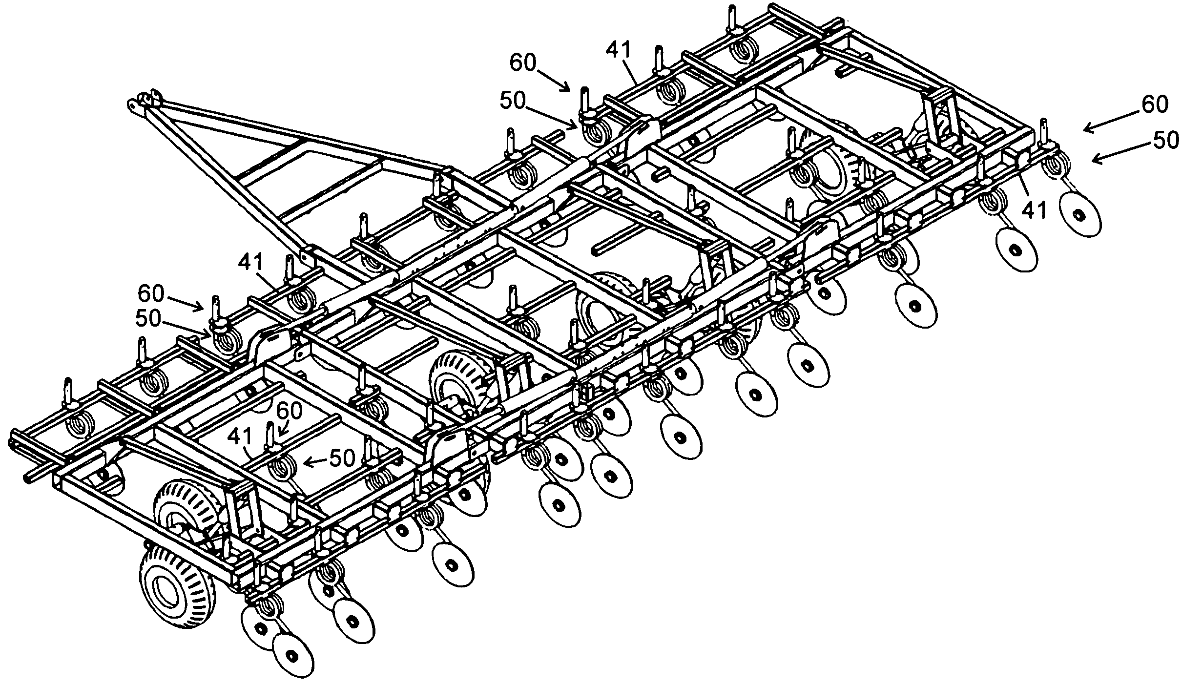
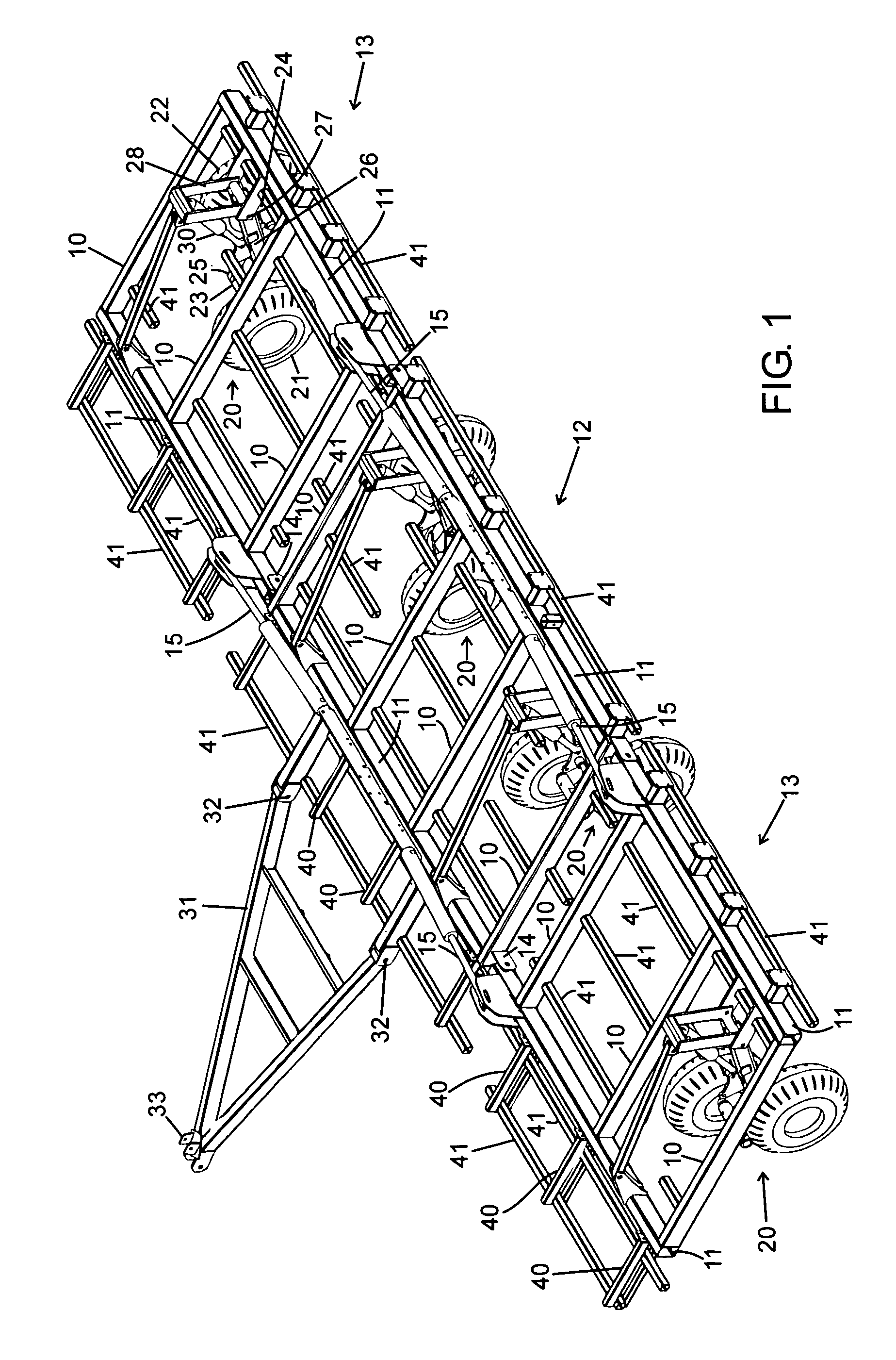
[0056]Referring to FIG. 1, a cultivator frame comprises a plurality of longitudinal 10 and transverse 11 rectangular steel tubes welded together to form a generally rectangular structure. The cultivator frame comprises a central portion, generally denoted as 12, and two wing portions, generally denoted as 13. Each wing portion 13 is attached to a side of the central portion 12 by means of hinges 14. Each wing portion 13 has a corresponding hydraulic cylinder means 15 mounted to the central portion 12 and operatively connected to each wing portion. Each wing portion 13 is able to pivot from a horizontal ground working orientation to a vertical transport orientation upon actuation of the hydraulic cylinder means 15.

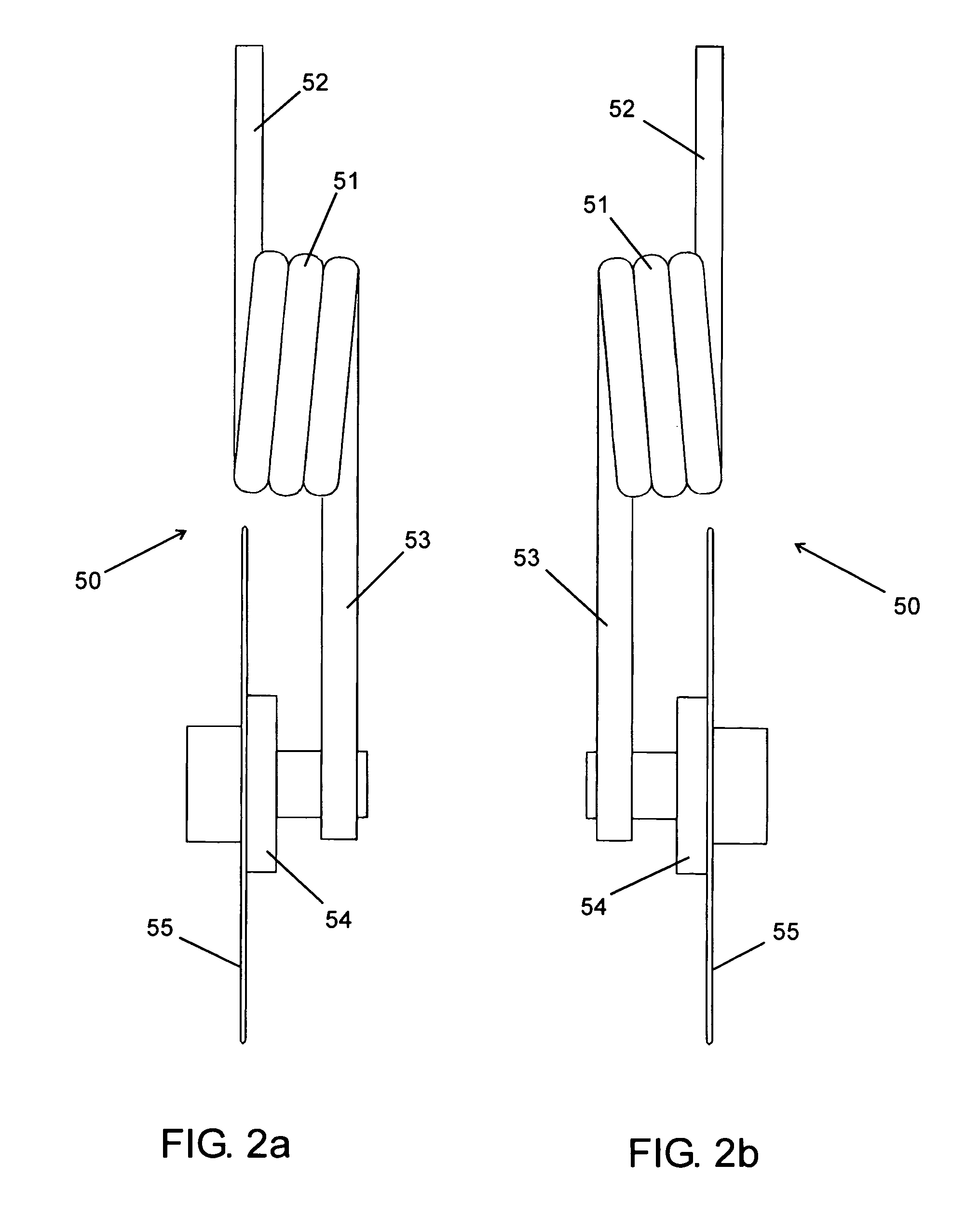
[0057]The cultivator frame has a set of wheels comprising four laterally spaced apart pairs of wheels 20. Only one such pair of wheels is labeled in detail. Eac...


PUM


Abstract

A conservation tillage implement having three or more rows of individual coulter wheel assemblies laterally spaced apart and removably mounted on a cultivator frame, a coulter wheel assembly in a given row being staggered with respect to the coulter wheel assemblies in a longitudinally adjacent row. The coulter wheel assemblies may be laterally adjustable and may be mounted to the cultivator frame using a mounting means that permits rotation about a vertical axis. The coulter wheel assemblies may comprise a coil spring having a horizontal spring axis to permit upward deflection in response to impact with an obstacle. Leveling attachments may optionally be mounted to the cultivator frame, along with additional field working tools. The implement is used in the management of crop residue as part of a minimum tillage strategy. The implement is particularly resistant to plugging and can be operated at high speeds without undue damage upon impact with obstacles. Advantageously, the implement can be operated in standing water, as found in the growing of rice.

Description

CROSS-REFERENCE TO RELATED APPLICATIONS[0001]This application is a 35 U.S.C. 371 of International Application PCT / CA2004 / 000339 filed Mar. 5, 2004. This application claims the benefit of U.S. Provisional Application No. 60 / 451,666 filed Mar. 5, 2003.FIELD OF THE INVENTION[0002]The present invention relates to an apparatus, system and method for minimally tilling a field as part of a conservation tillage strategy. More particularly, the present invention relates to an apparatus system, and method for crop residue management.BACKGROUND OF THE INVENTION[0003]Plant residue is plant material that remains in a field following a particular growing season. Plant residue includes roots, stem, leaves and seed bearing or enclosing plant structures (e.g. pods, cobs and husks) originating from plants present in the field during the previous growing season (eg: seeded crops, volunteer species and weeds). In order to plant a new crop in a field, plant residue from the previous crop must first be d...

Claims


Application Information

Patent Timeline
Patent Type & Authority Patents(United States)
IPC IPC(8): A01B7/00A01B35/16
CPCA01B35/16A01B35/28A01B49/02A01B61/046Y02A40/22Y02P60/20
Inventor ROZENDAAL, JACOBUS A.O'GRADY, PHILIP M.BOAK, JAMES F.AVERINK, JOHN M.GRAY, GEOF J.
Owner SALFORD GRP INC
Why Eureka
Try Eureka