Method and apparatus for measuring spectroscopic absorbance

a spectroscopic absorbance and absorbance technology, applied in the field of spectroscopic absorbance measurement, can solve the problems of inability to obtain the exact peak height of the impurity concentration of interest, inability to sufficiently remove the influence of phonon absorbance from the differential spectrum, etc., to achieve satisfactory baseline, enhance detection sensitivity, and effectively remove background influence

Active Publication Date: 2010-08-03
SUMCO TECHXIV
View PDF3 Cites 26 Cited by
  • Summary
  • Abstract
  • Description
  • Claims
  • Application Information

AI Technical Summary

Benefits of technology

[0016]According to a fourth aspect of the present invention, the method of measuring spectroscopic absorbance as recited in any one of the first to third aspects is provided, in which a spectroscopic absorbance peak due to the substitutional carbon in the differential spectrum is considered a signal, and a standard deviation of the differential absorbance in the wave number domain around the spectroscopic absorbance peak is considered noise, thereby allowing the calculation a signal-to-noise ratio of the infrared absorption differential spectrum due to the substitutional carbon.
[0020]According to the present invention, in cases where differential spectroscopy is used in spectroscopic absorbance measurement such as FT-IR, it is possible to effectively remove background influence, and to obtain a satisfactory baseline, thereby making it possible to enhance detection sensitivity as compared to conventional methods.
[0021]This method is extremely effective in determining impurity concentration in a silicon single crystal or the like.

Problems solved by technology

Accordingly, in cases where a wave number shift exists between the reference spectrum and the sample spectrum even to a minute extent, it is not possible to sufficiently remove the influence of phonon absorbance from the differential spectrum.
As a result, a sufficiently satisfactory baseline cannot be obtained, and the baseline is full of unevenness, leading to a problem that it is impossible to obtain an exact peak height of the impurity concentration of interest.

Method used


Image

  • Method and apparatus for measuring spectroscopic absorbance
  • Method and apparatus for measuring spectroscopic absorbance
  • Method and apparatus for measuring spectroscopic absorbance

Examples


example 1

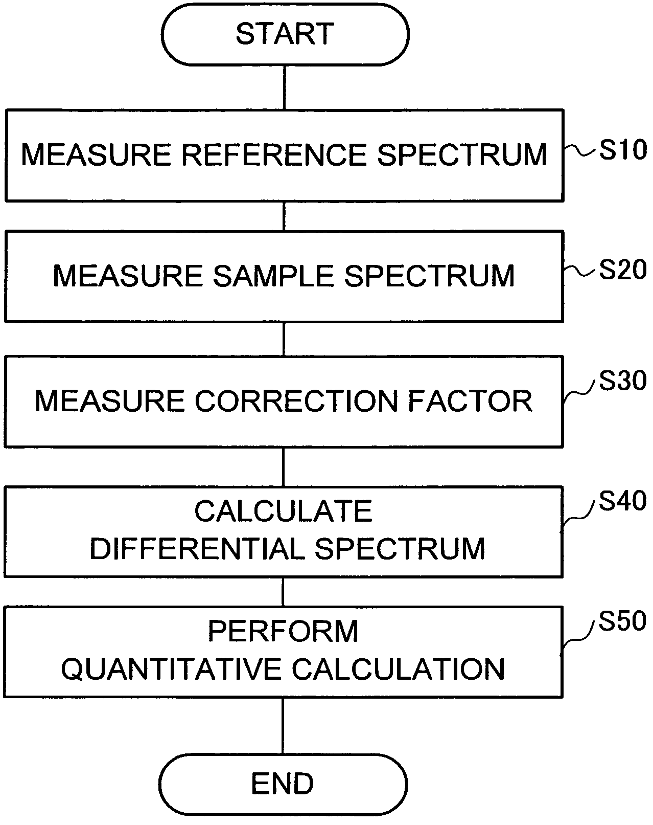
[0058]In Example 1, the wave number shift dependence of the differential spectrum in the method of the present invention is described. FIG. 3 is a diagram showing the wave number shift dependence of the differential spectrum, which is one embodiment of the present invention. As a reference sample, a substantially carbon-free CZ method silicon single crystal was used, and the range of wave numbers from 540 to 660 cm−1 was measured at a wave number resolution of 1 cm−1.

[0059]At first, an infrared spectroscopy spectrum (data R) of the reference sample was obtained, and an infrared spectroscopy spectrum (data S) of a measurement sample for quantitative determination of the concentration of substitutional carbon was obtained. Subsequently, by using a computer, a2 of Equation 3 was assigned a certain constant value shifting the wave number of data R to thereby obtain an infrared spectroscopy spectrum (data R′). In addition, a differential spectrum (data D) was obtained by using the least ...

example 2

[0063]In Example 2, the differential spectrum after correction in the method of the present invention is described. FIG. 4(a) is a differential spectrum after FT-IR correction for quantitative determination of substitutional carbon in a silicon single crystal, which is one embodiment of the present invention. As for the FT-IR differential spectrum using the wave number shift correction in the present invention, the transverse axis is wave number [cm−1], and the vertical axis is differential absorbance.

[0064]As described in Example 1, the method of calculating a differential spectrum is as follows. A reference spectrum obtained from a substantially carbon-free reference sample and a measurement spectrum obtained from a measurement sample for the quantitative determination of the concentration of substitutional carbon were measured. Subsequently, a wave number shift amount, which satisfies the condition to minimize the sum of squared residual, and a baseline offset amount were determi...

example 3

[0068]In Example 3, the evaluation example of the detection limit in the method of the present invention is described. FIG. 5 is an example of evaluation by use of the concept of the signal-to-noise ratio (SN ratio), where the carbon peak height is a signal, and the data deviation in the right and left baseline region is noise, in a differential spectrum after correction which is one embodiment of the present invention. The actual measurement data was the same as the data of the aforementioned differential spectrum after correction in the present invention described with reference to FIG. 4 as well as the data of the differential spectrum in the conventional method, so the description of the overlapping portions will be omitted.

[0069]FIG. 5(a) is a differential spectrum after FT-IR correction for quantitative determination of substitutional carbon in a silicon single crystal. In this figure, the dotted line shows a baseline 166 for calculating a signal-to-noise ratio, and the solid ...


PUM

PropertyMeasurementUnit
spectroscopic absorbanceaaaaaaaaaa
differential spectroscopyaaaaaaaaaa
absorbanceaaaaaaaaaa

Abstract

An object of the present invention is to provide a spectroscopic method and an apparatus which can measure a trace element accurately with high sensitivity. In order to achieve this object, for example, in Fourier transformation infrared spectroscopy (FT-IR), a reference spectrum and a measurement spectrum including an impurity spectrum are measured in order to obtain a differential spectrum comprising the impurity spectrum and a flat baseline, correction including a frequency shift of the reference spectrum before calculating a differential spectrum, is performed on the reference spectrum. This makes it possible to remove baseline deformation due to phonon absorbance of silicon included in the conventional differential spectrum, and to obtain an infrared absorption spectrum of the substitutional carbon with high accuracy and high sensitivity.

Description

[0001]This application is based on and claims the benefit of priority from Japanese Patent Application No. 2008-001677, filed on 8 Jan. 2008, the content of which is incorporated herein by reference.BACKGROUND OF THE INVENTION[0002]1. Field of the Invention[0003]The present invention relates to a method of measuring spectroscopic absorbance such as Fourier transform infrared spectroscopy (FT-IR), and to an apparatus for measuring spectroscopic absorbance embodying the method.[0004]2. Related Art[0005]Conventionally, in the quality evaluation of a semiconductor producing process, FT-IR has been used to measure the concentration of substitutional carbon that is an impurity in a silicon single crystal. Specifically, a technique is known, in which differential spectroscopy is used to obtain an infrared absorption spectrum of substitutional carbon that is an impurity included in a measurement target (sample), by means of subtraction factor correction by subtracting an infrared absorption...

Claims


Application Information

Patent Timeline
Patent Type & Authority Patents(United States)
IPC IPC(8): G01J5/06G01N21/35G01N21/3563G01N21/3581G01N21/359
CPCG01J3/45G01N21/3563G01N2021/3568G01N2021/3595
Inventor NAGAI, KIYOSHISHIBATA, HARUMIHAMAGUCHI, SAYAKA
Owner SUMCO TECHXIV
Why Eureka
Try Eureka