Charge particle beam accelerator

a technology of charged particles and beam accelerators, which is applied in the direction of instruments, tubes with screens, heat measurement, etc., can solve the problems of unstable bundle of charged particles, affecting the acceleration efficiency of the accelerator,

Inactive Publication Date: 2010-08-03
EUCLID TECHLABS LLC
View PDF5 Cites 1 Cited by
  • Summary
  • Abstract
  • Description
  • Claims
  • Application Information

AI Technical Summary

Benefits of technology

[0010]The novel features of the present invention provide an object with a very important property, i.e. said property makes it possible to regulate the phase balance of the charged particle beam and the wave that accelerates the particles. The applicant hasn't found any sources of information containing data on charged particle beam accelerators comprising additional ferroelectric material layer and thereby providing the control of the accelerator parameters.

Problems solved by technology

A disadvantage of said accelerator consists in the fact that the bunch of charged particles is unstable and precipitates on the shell walls after a short transit.
A disadvantage of said engineering solution consists in the fact that the accelerator parameters cannot be controlled, and the lack of phase balance of the charged particle beam and the accelerating wave lowers the acceleration efficiency.

Method used


Image

  • Charge particle beam accelerator
  • Charge particle beam accelerator

Examples


Embodiment Construction

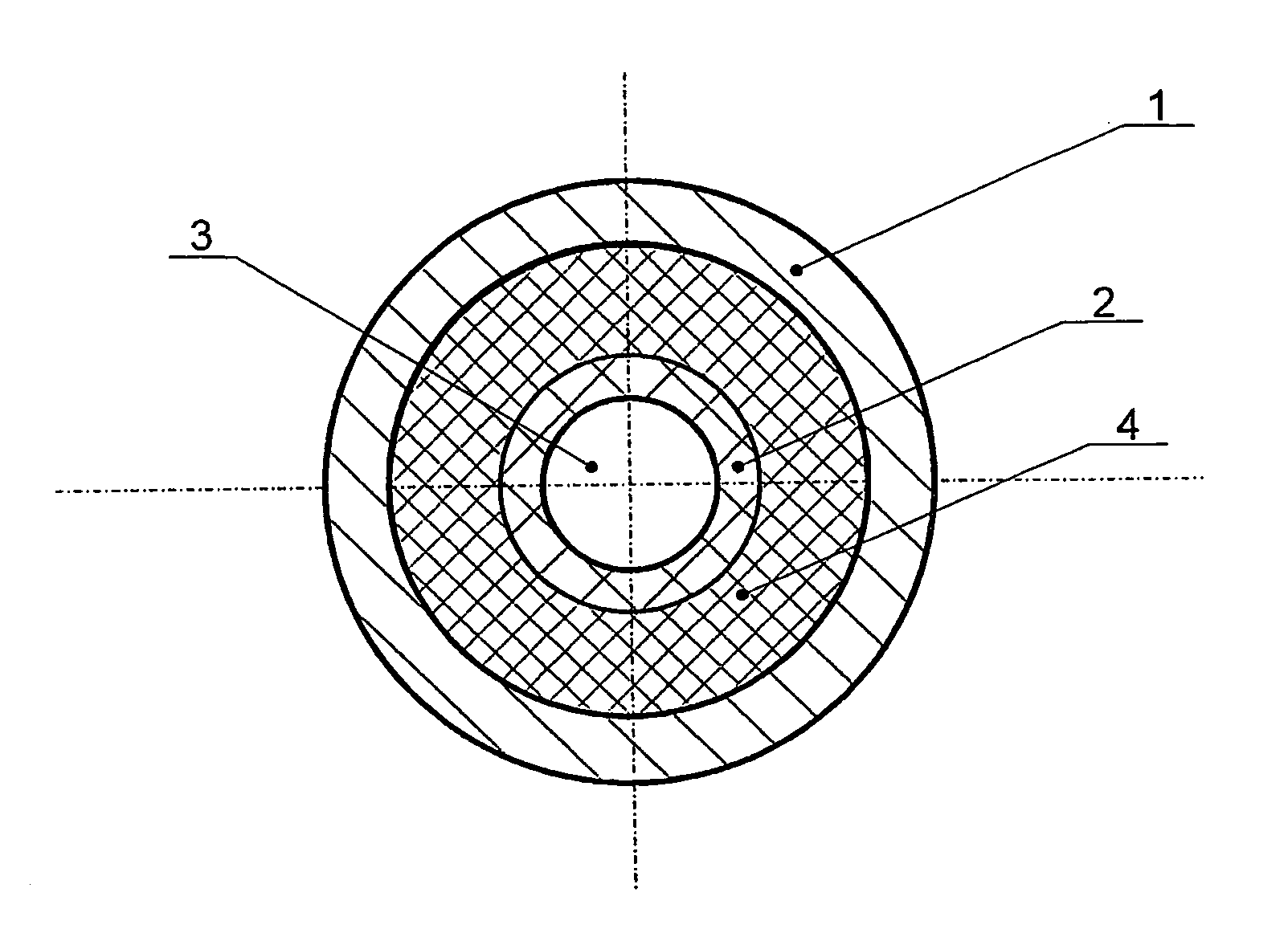
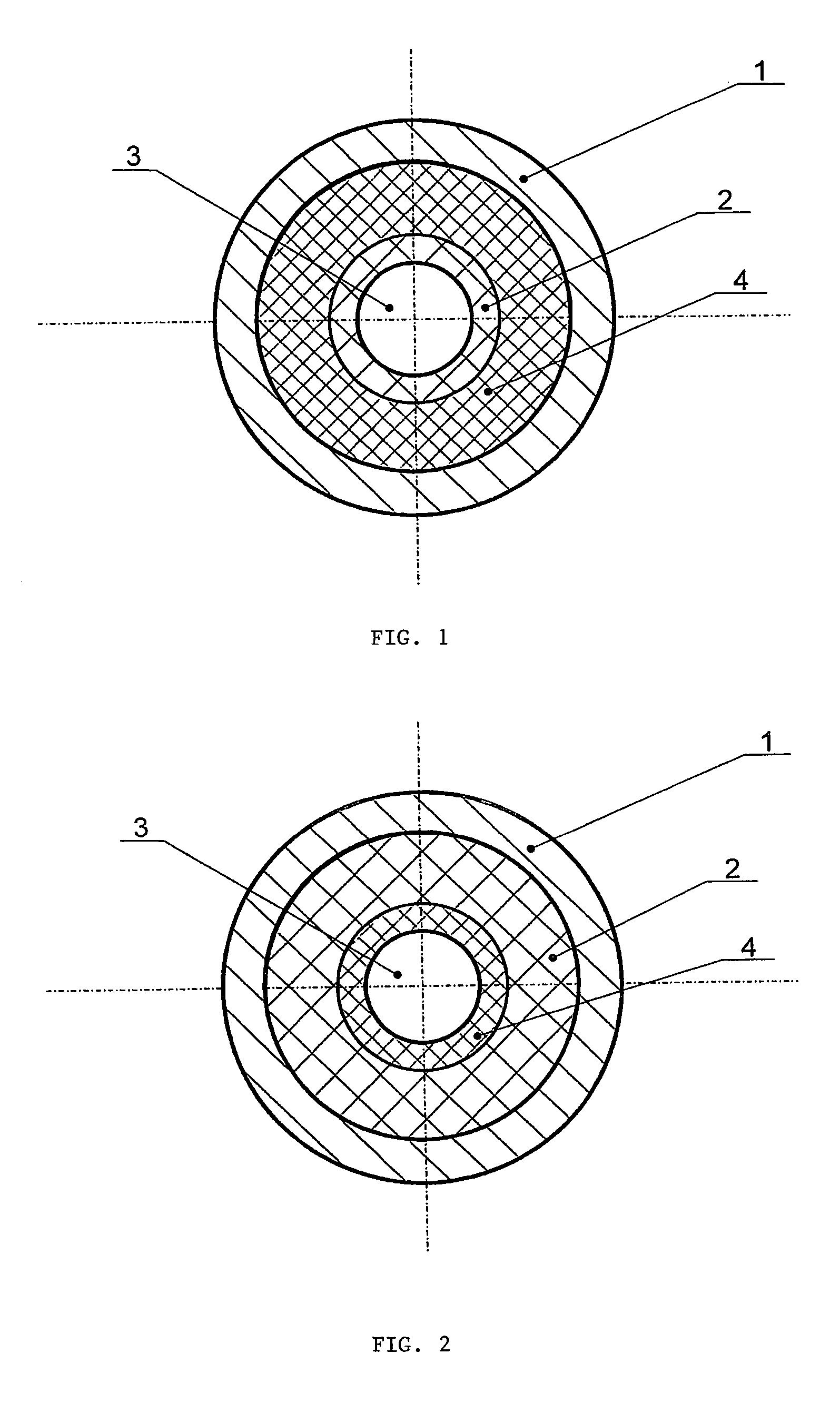
[0015]The charged particle beam accelerator comprises a metallic shell 1 fitted with a dielectric material layer 2 arranged therein and a vacuum channel 3 embodied along the central symmetry axis of said metallic shell 1. The dielectric material is any suitable high-frequency ceramic material with dielectric capacity (∈) between 4 and 45. The base of these dielectrics are the oxide systems—compounds and solid solutions, such as cordierite (2MgO.2Al2O3.5SiO2) having ∈≈4.7, corundum (Al2O3) having ∈≈9.7, magnesium and calcium titanates of the MgO—CaO—TiO2 system having ∈ between 14 and 20, as well as solid solutions of calcium titanate—rare-earth elements' aluminates CaTiO3—LnAlO3 (Ln—La, Nd) having ∈ between 38 and 45. The distinguishing feature of said class of dielectric materials is their considerably low dielectric loss in the microwave range.

[0016]The metallic shell 1 is fitted with an additional ferroelectric material layer 4. Said ferroelectric material layer can be arranged e...


PUM


Abstract

The invention relates to charged particle beam accelerators, in particular electron beam accelerators, and can be used for physics, chemistry and medicine. The inventive charged particle beam accelerator comprises a metallic shell fitted with a dielectric material layer arranged therein, and a vacuum channel for electron transit embodied along the central symmetry axis of said metallic shell. In addition, the metallic shell is fitted with a ferroelectric material layer arranged therein. Said ferroelectric material layer can be arranged between the metallic shell and the dielectric material layer or in said dielectric material layer. The invention provides an object with a very important property, i.e. said property makes it possible to control the accelerator parameters and regulate the phase balance of the charged particle beam and the wave that accelerates the particles.

Description

TECHNICAL FIELD[0001]The invention relates to charged particle beam accelerators, in particular electron beam accelerators, and can be used for physics, chemistry and medicine.BACKGROUND ART[0002]Known charged particle beam accelerator comprises a metallic shell fitted with a dielectric material layer arranged therein, and wherein said dielectric material layer is embodied in the form of a bar. In addition, said charged particle beam accelerator comprises vacuum channels for charged particle transit embodied between the metallic shell and the dielectric material and along the central symmetry axis inside the dielectric material (see Rhon Keining et al. “ANNULAR BEAM DRIVEN HIGH GRADIENT ACCELERATORS”, proceedings of the 7th International Conference “High-Power Particle Beams”, 1988, pp. 864-869”).[0003]A disadvantage of said accelerator consists in the fact that the bunch of charged particles is unstable and precipitates on the shell walls after a short transit.[0004]Another known c...

Claims


Application Information

Patent Timeline
Patent Type & Authority Patents(United States)
IPC IPC(8): F03H1/00H05H5/02H05H15/00
CPCH05H15/00
Inventor KANAREIKIN, ALEXEI DMITRIEVICHNENASHEVA, ELIZAVETA ARKADIEVNA
Owner EUCLID TECHLABS LLC
Why Eureka
Try Eureka