
Method for aberration evaluation in a projection system

a projection imaging and aberration evaluation technology, applied in the field of aberration evaluation of projection imaging systems, can solve the problems of difficult field use (or in-situ application), inability to use rayleigh /4 rule for high resolution applications, and inability to distinguish aberrations, etc., and achieve the effect of easing the difficulty of aberrations

Inactive Publication Date: 2010-08-03
SMITH BRUCE W
View PDF6 Cites 2 Cited by
  • Summary
  • Abstract
  • Description
  • Claims
  • Application Information

AI Technical Summary

Benefits of technology

"The invention provides a method for detecting lens aberration in a projection system through an open figure test target that has multiple component arrays of phase zones that respond uniquely to specific aberrations. This method offers the advantage of sensitivity to various aberration types and the ease with which aberrations can be distinguished. The test target has no boundary line and the interrelationship among the multiple phase geometry allows for the detection of aberration using the open figure test target. The method is unique and not obvious based on previous disclosures."

Problems solved by technology

This Rayleigh λ / 4 rule is not suitable however for high resolution applications such as microlithographic imaging or micro-optical inspection applications.
A more significant limitation of these interferometric methods in the need for the reference and test beams to follow separated paths, making field use (or in-situ application) difficult.
One is therefore restricted to using alternative approaches to measure, predict, approximate, or monitor lens performance and aberration during application of the optical system.

Method used


Image

  • Method for aberration evaluation in a projection system
  • Method for aberration evaluation in a projection system
  • Method for aberration evaluation in a projection system

Examples


Embodiment Construction

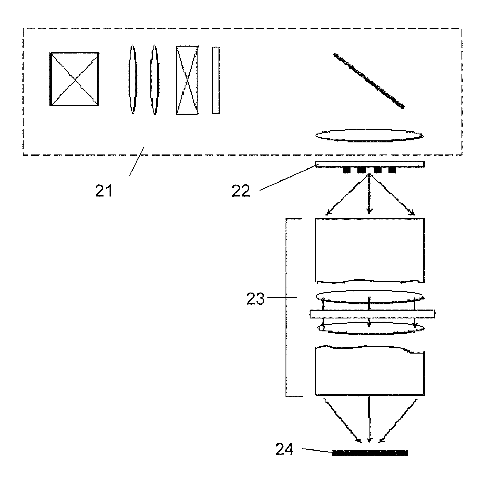
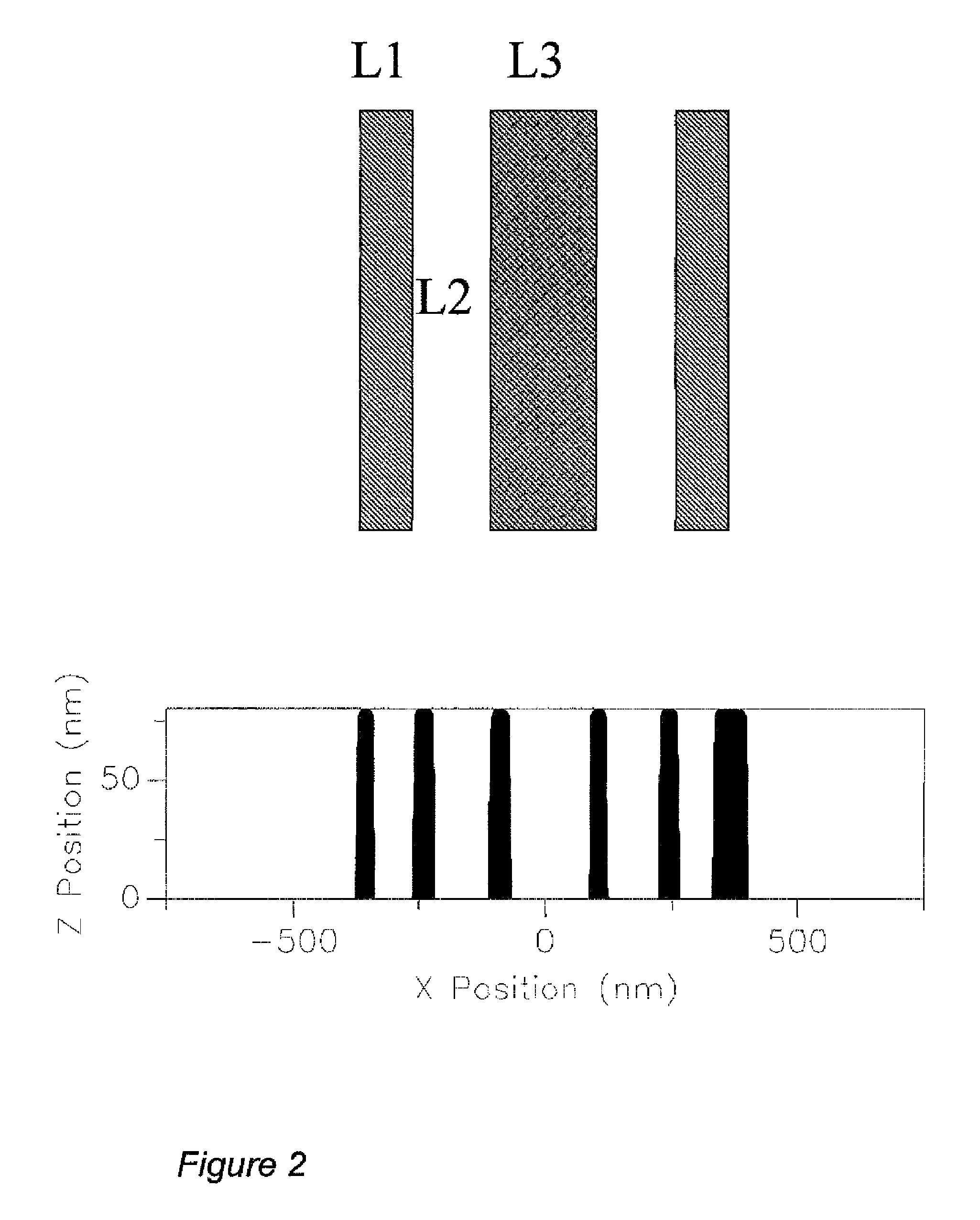
[0039]When imaging with a projection optical system, the aberrations in the lens pupil introduce deformation to a wavefront resulting in imaging errors. FIG. 7 shows a schematic of a projection imaging system. An illumination apparatus 21 illuminates a mask test object 22 which is imaged through an objective lens 23 onto a photosensitized substrate 24. If a test object is employed on a photomask as a phase pattern, specifically with a phase shifted from that of the surrounding area by 180 degrees, the lens aberration will introduce imaging errors characteristic of the aberration type and the mask geometry. As an example, FIG. 2 shows how three small phase lines (between 0.5 and 1.5 lambda / NA) are printed into a photoresist. The images are a result of lithographic simulation using a Prolith vector model (Prolith Version 7.0, KLA FINLE) with a wavelength of 157 nm, a numerical aperture (NA) of 0.85, a partial coherence value of 0.30, and a resist thickness of 80 nm. The resulting imag...


PUM

PropertyMeasurementUnit
wavelengthsaaaaaaaaaa
thicknessaaaaaaaaaa
thicknessaaaaaaaaaa

Abstract

Aberrations in an optical system can be detected and measured using a method comprised of a test target in the object plane of a projection system and imaging onto the image plane with the system. The test target comprises at least one open figure which comprises a multiple component array of phase zones, where the multiple zones are arranged within the open figure so that their response to lens aberration is interrelated and the zones respond uniquely to specific aberrations depending on their location within the figure. This is a unique and new method of detecting a variety of aberration types including coma, spherical, astigmatism, and three-point through the imaging onto photosensitive material or image detector placed in the image plane of the system and the evaluation of these images. The method of the invention offers an advantage over other methods because of the sensitivity to particular aberration types, the unique response of the multiple zones of the test target to aberrations, and the ease with which aberrations can be distinguished.

Description

CROSS REFERENCE TO RELATED APPLICATIONS[0001]This application is a Continuation in Part of U.S. patent application Ser. No. 10 / 734,462 filed Dec. 12, 2003, which claims the benefit of the priority date of U.S. Provisional patent application Ser. No. 60 / 433,153 filed Dec. 13, 2002.FIELD OF THE INVENTION[0002]The present invention relates to aberration evaluation of a projection imaging system.BACKGROUND OF THE INVENTION[0003]Optical lithography has been the dominant technology for the patterning of semiconductor device features. As the size of the geometry for these devices continue to shrink below the ultraviolet (UV) wavelength used for imaging, significant demands are placed on the quality of the optical component within the projection imaging system. Projection systems used for microlithographic imaging or micro-optical inspection comprise a large number of lens elements and operate at wavelengths ranging from 436 nm to 126 nm. The level of aberration in these systems must be low...

Claims


Application Information

Patent Timeline
Patent Type & Authority Patents(United States)
IPC IPC(8): G01N21/55G03B27/68G03F7/20
CPCG03F7/706
Inventor SMITH, BRUCE W.
Owner SMITH BRUCE W
Learn More