Method and apparatus for adjusting for polarization-induced, optical signal transients

Active Publication Date: 2010-08-03
AMERICAN TELEPHONE & TELEGRAPH CO
View PDF17 Cites 11 Cited by
  • Summary
  • Abstract
  • Description
  • Claims
  • Application Information

AI Technical Summary

Benefits of technology

[0018]In one advantageous embodiment of the invention, two depolarized reference signals are used to eliminate the uncertainty caused by polarization effects. The reference signals comprise at least one known characteristic which can be measured or estimated at two points on a fiber optic network, such as at the beginning and end of a fiber optic link. A DGTC or ot

Problems solved by technology

Dynamic, transparent, optical networking results in improved transport economics and flexibility, but creates new problems such as the introduction of optical transients associated with adding and dropping channels into an optical transmission path.
However, in operation, achieving such consistency with OAs is very difficult to realize.
It is not always practical and can be costly to recalibrate or replace OAs whose efficacy has diminished.
However SRS can also be a side effect of normal transmission of optical signals through a fiber, and, as such, can be a source of spurious light that results in signal degradation.
Yet another cause of signal degradation is crosstalk which occurs when a signal at one wavelength interferes with the signal at another wavelength.
A Raman amplifier with a single pump may fail to provide gain over the bandwidth required in some WDM optical systems.
However, the gain spectrum from each pump tends to overlap such that a multi-pump Raman amplifier typically exhibits some variation in gain over the spectral range of the amplifier, known as “ripple.” This disparity in imparted gain can negatively affect signal quality and thus, maximum

Method used


Image

  • Method and apparatus for adjusting for polarization-induced, optical signal transients
  • Method and apparatus for adjusting for polarization-induced, optical signal transients
  • Method and apparatus for adjusting for polarization-induced, optical signal transients

Examples


first embodiment

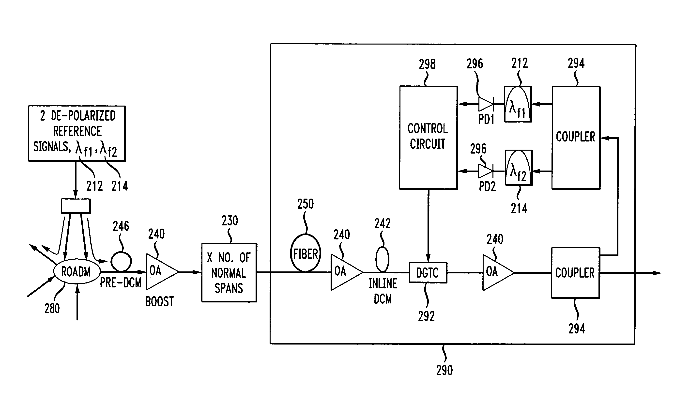
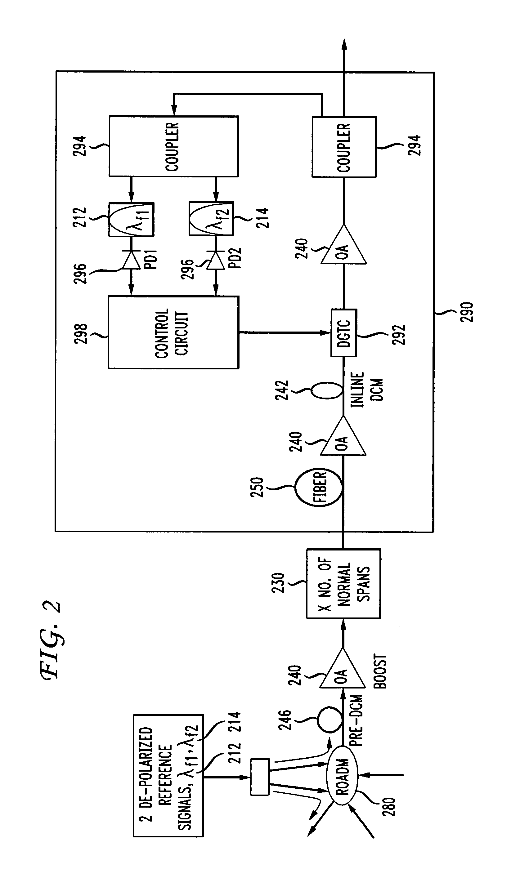
[0036]FIG. 2 shows the invention where two depolarized reference channels or signals 212 and 214 are used to eliminate the uncertainty caused by polarization effects. The reference signals 212 and 214 have different wavelengths and are added or multiplexed by means of a ROADM 180 into a fiber optic link containing a plurality of channels. The reference signals comprise at least one known characteristic which can be measured or estimated at two points on a fiber optic network, such as at the beginning and end of a fiber optic link. Alternatively, a polarization scrambler may be utilized which scrambles the states of polarization of the two reference signals 212 and 214. Reference numbers on FIG. 2 correspond to the reference numbers of FIG. 1. For example, reference signal 112 in FIG. 1 is reference signal 212 in FIG. 2. The reference signals 212 and 214 may be any depolarized light beam known in the art such as from a Distributed Feedback laser or a Fiber Bragg grating stabilized Fa...

second embodiment

[0043]FIG. 4a shows the invention where total optical power of all channels is measured in addition to the power of the reference channels. The total optical power is the sum of the power transmitted in each channel propagating in the optical network. Reference numbers in FIG. 4a correspond to the reference numbers of FIG. 3. For example, reference signal 312 in FIG. 3 is reference signal 412 in FIG. 4a. As above, elements of FIG. 4a which correspond to elements in FIGS. 2 and 3 are given similar numbers. In this embodiment, a 1:2 coupler 494 sends the signals to be measured from the fiber optic cable 450 to the control circuit 498 by way of a 1:3 coupler 495 then separates the signal into the reference signal 412, reference signal 414, and entire transmitted signal. In this embodiment of the invention, the reference signals 412 and 414 are polarized.

[0044]FIG. 4b shows the total optical power in dBm as a function of gain difference in dB in the second embodiment. As optical power i...

third embodiment

[0048]FIG. 5 shows the invention where gain tilt is estimated from the total optical power. This measurement is used to adjust the tilt at the DGTC 592. This method proceeds by measuring total optical power transmitted in the optical link and the power in one reference signal 512. In this embodiment, the reference signal 512 may be polarized, depolarized, or scrambled. When the reference signal 512 is polarized, the amount of tilt can be estimated based on a comparison between the total optical power and optical power of the reference signal. For example, when the variation in the total optical power is relatively small and the measured relative power variation of the polarized reference signal is relatively large, it can be deduced that a polarization event has taken place which has affected the signal. This measurement can be used to compensate for the polarization effects.


PUM


Abstract

The invention includes methods and apparatuses to adjust an optical signal transmitted through an optical amplifier, such as in a wavelength division multiplexed optical network. The methods and apparatus of the invention calculate polarization effects which cause degradation to the optical signal. A measurement of the polarization-related degradation of an optical signal is calculated by using at least one reference signal. In some embodiments of the invention, the reference signal is depolarized or has scrambled polarizations. The invention is typically used in long-haul optical networks.

Description

FIELD OF THE INVENTION[0001]The present invention relates to dynamic optical networks and more particularly relates to improvements in the performance of such networks.BACKGROUND OF THE INVENTION[0002]The current trend in optical transmission networks is toward longer transmission distances with reduced signal regeneration, and the use of remotely re-configurable optical add / drop multiplexers (ROADM) to bring signals on and off the network backbone. ROADMs can be reconfigured dynamically in a process that is transparent to users. Current transmission distances reach ranges of 600 to 10,000 kilometers. Dynamic, transparent, optical networking results in improved transport economics and flexibility, but creates new problems such as the introduction of optical transients associated with adding and dropping channels into an optical transmission path. Signal attenuation also occurs due to a variety of factors including scattering, absorption, and bending. To compensate for signal loss an...

Claims


Application Information

Patent Timeline
IPC IPC(8): H04B10/00H04B10/08H04B17/00
CPCH04B10/0775H04B10/296H04B10/532H04J14/021H04J14/0221
Inventor BIRK, MARTINZHOU, XIANG
Owner AMERICAN TELEPHONE & TELEGRAPH CO
Why Eureka
Try Eureka