Methods for manufacturing tuning-fork type piezoelectric vibrating devices

a piezoelectric vibrating device and tuning fork technology, applied in the direction of generator/motor, device material selection, instruments, etc., can solve the problems of unfavorable vibration frequency and/or ci value fluctuation otherwise caused by the different coefficients of thermal expansion, and frequency fluctuations. , the effect of reducing the fluctuation of vibration frequency and/or ci valu

Inactive Publication Date: 2010-08-10
NIHON DEMPA KOGYO CO LTD
View PDF4 Cites 3 Cited by
  • Summary
  • Abstract
  • Description
  • Claims
  • Application Information

AI Technical Summary

Benefits of technology

[0010]The various manufacturing methods disclosed herein provide piezoelectric vibrating devices having a base and vibrating arms. At least a pair of arms extends from the base, and each arm includes grooves in predetermined positions. These and other predetermined positions are readily achieved by the subject methods. More specifically, the grooves are thinner regions of the arms. In these grooves, one or more regions can be located that comprise only the first metal film. Thinner portions of the arms are influenced more by thermal expansions of the second metal film relative to thermal expansions of the first metal film. By having selected regions of the groove include only the first metal film, fluctuations of the vibration frequency and / or of the CI value caused by differences in the coefficients of thermal expansion of the first and second metal films are reduced.
[0011]According to another aspect, tuning-fork type piezoelectric vibrating devices are provided. An embodiment of such a device comprises a base made of a piezoelectric material and at least a pair of vibrating arms extending from an edge of the base in a predetermined direction. The vibrating arms have grooves on which a first single metal film is formed of one or more of chrome (Cr), nickel (Ni), and titanium (Ti). A second metal film, having a higher coefficient of thermal expansion than the first metal film, is not formed on these surfaces in the grooves. As a result, fluctuations of vibration frequency and / or of CI value otherwise caused by the different coefficients of thermal expansion are reduced.
[0012]Another embodiment of a tuning-fork type piezoelectric vibrating device includes “weights” formed on distal surfaces of the vibrating arms. To form the weights, a second metal film can be formed on the first metal film over selected regions of the arms including intended weighted regions. Each weight is an area of the first and second metal films formed at a respective distal region of a vibrating arm. Adjustment of the vibration frequency of the arm is performed simply by selective removal of the first and second metal films from the weight region. By forming predetermined portions of the electrodes on the piezoelectric vibrating device as single metal layers rather than multiple layers of metal, frequency fluctuations that otherwise would be exhibited during thermal processes are reduced. In addition, since the second metal layer is substantially more limited in scope than the first metal layer, the amount of metal used for forming the second layer is less, which reduces cost.

Problems solved by technology

These double-layer structures cause the tuning-fork type piezoelectric vibrating devices generally to exhibit undesirable stress on their vibrating-arm portions due to the different respective coefficients of thermal expansion of the crystal material and of gold (Au).
The stress imparts undesired change to the vibrational frequency produced by the vibrating device (as defined by its shape), and the change in frequency causes undesired fluctuation of the CI value of the vibrating device.
CI fluctuation undermines the vibration stability of vibrating device and produces excessive energy loss.

Method used


Image

  • Methods for manufacturing tuning-fork type piezoelectric vibrating devices
  • Methods for manufacturing tuning-fork type piezoelectric vibrating devices
  • Methods for manufacturing tuning-fork type piezoelectric vibrating devices

Examples


Embodiment Construction

Tuning-Fork Type Crystal Vibrating Device 20

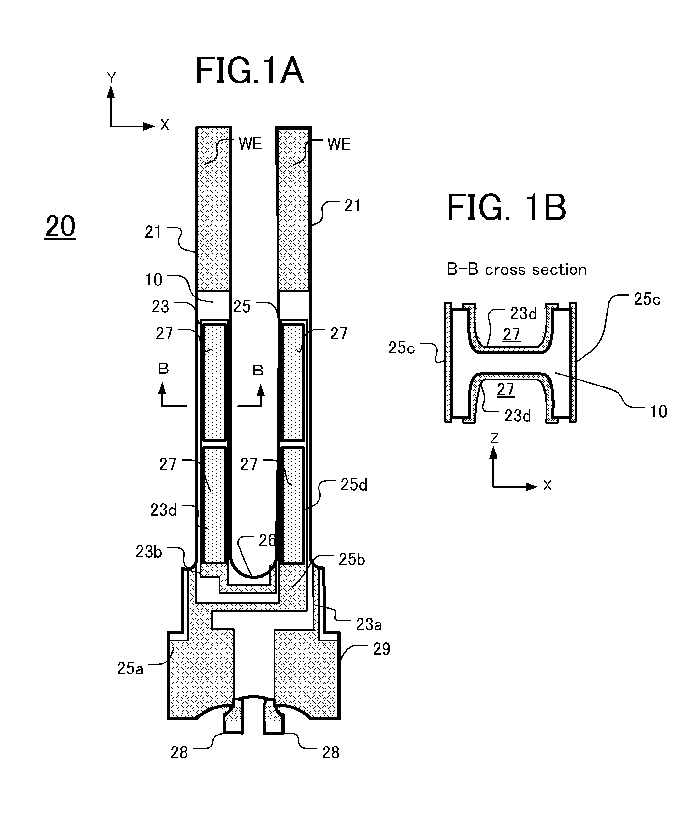
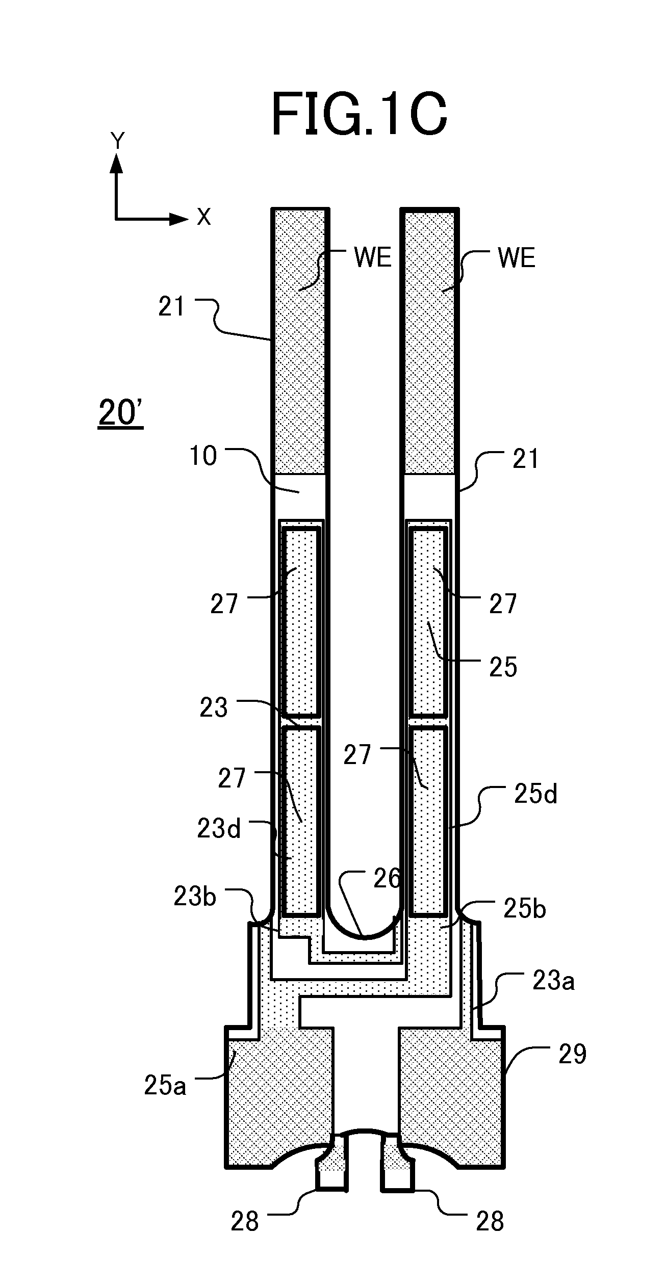
[0025]FIG. 1A is a schematic depiction of the configuration of an embodiment of a tuning-fork type crystal vibrating device 20, and FIG. 1B is a cross-sectional view along the line B-B of FIG. 1A. The line B-B extends across one of the vibrating arms 21 of the device 20. To achieve the required degree of miniaturization and high quality, as shown in FIG. 1A, the device 20 comprises a base 29 and a pair of vibrating arms 21 extending from the base 29. The arms extend parallel to each other, in a tuning-fork configuration, from a top edge of the base 29. A crotch portion 26 of the pair of arms 21 includes a tapered or rounded region that reduces changes in or fluctuation of the resonance frequency of the arms that otherwise would be caused by ambient temperature changes. A V-shaped crotch portion 26 provides the tapered region, and a U-shaped crotch portion 26 (shown) provides the rounded region. This embodiment is described below with refer...


PUM

PropertyMeasurementUnit
vibration frequencyaaaaaaaaaa
diameteraaaaaaaaaa
thicknessaaaaaaaaaa

Abstract

In an exemplary method a profile outline of a desired piezoelectric vibrating piece is formed on a surface of a piezoelectric wafer. The piece includes a base and at least two arms extending from the base. On a surface of the wafer within the profile outline, a first metal layer is formed comprising at least one of Cr, Ni, and Ti. A second metal layer, of Au and / or Ag, is formed on at least one selected region of the first metal layer. An electrode pattern is formed on at least one selected region of the second metal layer. From at least one selected location within the electrode pattern, the second metal layer is peeled away to form an electrode on the piezoelectric vibrating device comprising the first metal layer but not the second metal layer.

Description

CROSS-REFERENCE TO RELATED APPLICATIONS[0001]This application claims priority to, and the benefit of, Japan Patent Application No. 2007-227340, filed on Sep. 3, 2007, in the Japan Patent Office, the disclosure of which is incorporated herein by reference in its entirety.FIELD[0002]This disclosure relates to, inter alia, piezoelectric vibrating devices, particularly devices having a “tuning-fork” configuration, and to methods for manufacturing such devices. The subject methods produce piezoelectric vibrating devices having particular electrode patterns and other features.DESCRIPTION OF RELATED ART[0003]Various types of clocks, home electric appliances, and consumer electronics, and various types of commercial / industrial electrical apparatus such as information / communication devices and Office-Automation devices utilize at least one oscillator. These oscillators typically are manufactured by packaging a piezoelectric resonator, a piezoelectric vibrating device, or an IC tip as a clock...

Claims


Application Information

Patent Timeline
Patent Type & Authority Patents(United States)
IPC IPC(8): H04R17/00H01L41/047H01L41/09H01L41/18H01L41/22H01L41/29H01L41/332H03H3/02H03H9/19
CPCG01C19/5607H01L41/1132H03H3/04H03H9/1021H01L41/29H03H9/21Y10T29/49155H03H2003/026Y10T29/42Y10T29/49574H10N30/302H10N30/06
Inventor TAKAHASHI, TAKEHIRO
Owner NIHON DEMPA KOGYO CO LTD
Why Eureka
Try Eureka